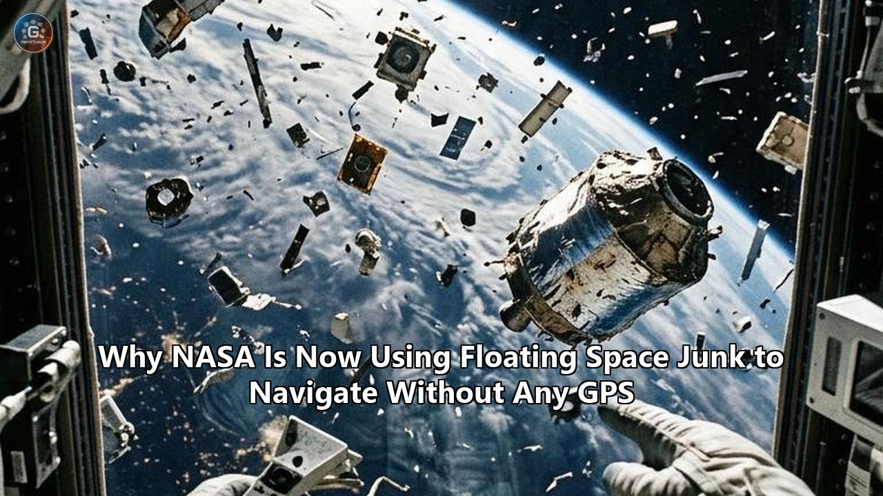
In August 2026, flight controllers at NASA’s Ames Research Center and engineers from aerospace startup EraDrive verified that a swarm of shoebox-sized satellites orbiting 565 kilometers above Earth had calculated their positions, maintained orbital station-keeping, and refined the flight paths of neighboring orbital objects without receiving a single radio transmission from Earth or locking onto a single Global Positioning System (GPS) signal.
The flight experiment, conducted aboard NASA’s Starling technology demonstration mission, demonstrated a capability known as FALCON: Fast Autonomous Lost-in-space Catalog-based Optical Navigation. Over a three-day operational window, Starling’s onboard star trackers—small, low-power optical cameras originally designed merely to determine which way the spacecraft is pointing—were repurposed to track non-cooperative resident space objects (RSOs). The spacecraft observed spent rocket stages, defunct payloads, and fragmented orbital debris drifting across the starfield. By comparing the observed angular trajectories of this floating debris against a compressed onboard catalog of roughly 20,000 tracked objects, the spacecraft solved its own absolute position and velocity while simultaneously improving the orbital trajectory estimates for more than 200 cataloged debris objects.
+-------------------------------------------------------------------------+
|                        FALCON FLIGHT TEST AT A GLANCE                   |
+-------------------------------------------------------------------------+
| Host Platform       | NASA Starling Swarm (4x 6U CubeSats)              |
| Orbit / Altitude    | Low Earth Orbit (LEO) ~565 km, 97.7° Inclination  |
| Primary Payload     | EraDrive Era-Core Autonomous Flight Software      |
| Sensor Suite        | Repurposed Commercial Off-The-Shelf Star Trackers |
| Onboard Database    | Compressed Ephemeris Catalog (~20,000 RSOs)       |
| Flight Results      | Full absolute orbit determination without GPS;    |
|                     | >200 debris orbits refined beyond ground accuracy |
+-------------------------------------------------------------------------+
This flight validation marks a clear pivot in how space agencies and autonomous systems interact with orbital space. For decades, the millions of pieces of man-made debris encircling Earth have been treated exclusively as an operational hazard—a crowded minefield threatening active missions with catastrophic hypervelocity collisions. The FALCON trial converts that liability into a functional navigation constellation.
Analyzing the Starling FALCON experiment reveals how this operational test reflects broader shifts across aerospace engineering: the decoupling of critical orbital infrastructure from vulnerable Earth-based links, the convergence of Space Domain Awareness (SDA) with onboard Guidance, Navigation, and Control (GNC), and the rise of environmental opportunism in autonomous robotics.
The Starling-FALCON Case: Repurposing Vision at 7.6 Kilometers per Second
NASA’s Starling mission was launched into low Earth orbit (LEO) in July 2023 to evaluate multipoint autonomy, inter-satellite networking, and automated swarm maneuvers. The platform consists of four 6U CubeSats, each measuring approximately $10 \times 20 \times 30$ centimeters. While these nanosatellites carry GPS receivers for baseline validation, their core objective has been testing edge computing paradigms that eliminate external dependencies.
+---------------------------------------------------------------------------+
|               STARLING RECONFIGURED SENSOR ARCHITECTURE                   |
+---------------------------------------------------------------------------+
|                                                                           |
|   Standard Baseline Setup:                                                |
|   [Optical Star Tracker] -------------> Spacecraft Attitude (Orientation) |
|   [GPS Receiver Engine] --------------> Spacecraft Position & Velocity    |
|                                                                           |
|   FALCON Operational Setup:                                               |
|   [Optical Star Tracker] -----+-------> Spacecraft Attitude (Orientation) |
|                               |                                           |
|                               +-------> Detects Moving RSOs / Debris      |
|                                         |                                 |
|                                         v                                 |
|   [Compressed Catalog (20k)] ------> [Era-Core Filter Engine]             |
|                                         |                                 |
|                                         +---> Host Satellite Orbit State  |
|                                         +---> Refined Debris Ephemerides  |
|                                                                           |
+---------------------------------------------------------------------------+
To execute the FALCON trial, NASA partnered with EraDrive, an autonomous spacecraft navigation firm founded by researchers from Stanford University’s Space Rendezvous Laboratory (SLAB). The investigation loaded EraDrive’s proprietary flight software, Era-Core, directly onto Starling’s existing flight computers.
The primary challenge was operational: Starling carries no specialized space-surveillance radar, no ladar ranging instruments, and no high-gain active tracking sensors. The spacecraft relied entirely on commercial off-the-shelf (COTS) star cameras. These optical sensors are engineered to capture wide-field images of the celestial sphere, cross-reference stellar patterns against star tables such as the Hipparcos or Tycho-2 catalogs, and output attitude quaternions to describe spacecraft orientation.
          +-------------------------------------------------------+
          |           OPTICAL SENSOR FOCAL PLANE (2D CCD)         |
          |                                                       |
          |     * Star (Fixed Inertial Frame)                     |
          |                                                       |
          |                 * Star                                |
          |                                                       |
          |         -----\                                        |
          |               \==> [Debris Streak / Passing RSO]      |
          |                     (Time-Varying Angular Rate)       |
          |                                                       |
          |     * Star                                            |
          |                                    * Star             |
          +-------------------------------------------------------+
During the experiment, the software altered how these frames were processed:
- The camera captures an exposure of the starfield.
- Static background stars are recognized and used to establish the camera's precise inertial attitude reference frame.
- Unmatched, high-speed luminous targets crossing the field of view—which standard attitude algorithms discard as sensor noise, hot pixels, or cosmic ray anomalies—are isolated.
- The algorithm computes the target’s line-of-sight unit vector across sequential frames to extract time-stamped bearing angles.
- These bearing angles are fed into an onboard estimator that matches observed angular rates against the candidate orbital paths of 20,000 objects in its memory.
- A batch and sequential orbit determination filter simultaneously refines the host spacecraft's position vector and the observed targets' orbital elements.
+--------------------------------------------------------------------------+
|                     FALCON DATA PROCESSING PIPELINE                      |
+--------------------------------------------------------------------------+
|                                                                          |
|  [ Raw Camera Frame ]                                                    |
|           |                                                              |
|           v                                                              |
|  [ Star Identification & Calibration ]                                   |
|           |                                                              |
|           +------> Inertial Attitude Determination                       |
|           v                                                              |
|  [ Background Star Subtraction & Thresholding ]                          |
|           |                                                              |
|           v                                                              |
|  [ Non-Stellar Streak / Centroid Extraction ]                            |
|           |                                                              |
|           v                                                              |
|  [ Track Association vs. Onboard 20,000-Object Catalog ]                 |
|           |                                                              |
|           v                                                              |
|  [ Batch Initial Orbit Determination (IOD) Differential Corrector ]      |
|           |                                                              |
|           v                                                              |
|  [ Sequential Extended / Unscented Kalman Filter ]                       |
|           |                                                              |
|           +------> Spacecraft Absolute State (Position/Velocity)         |
|           +------> Debris Orbital Parameter Ephemeris Updates            |
|                                                                          |
+--------------------------------------------------------------------------+
The system requires no cooperation from the observed target. The debris does not need to broadcast a beacon, ping a transponder, or reflect specialized laser wavelengths. It is merely an inert piece of metal or composite material, illuminated by solar radiation, drifting through the vacuum according to the laws of orbital mechanics.
By watching these uncooperative, passive objects move relative to the fixed celestial background, the Starling satellites verified their absolute position in low Earth orbit with an accuracy sufficient for autonomous station-keeping and trajectory maintenance. In doing so, they also produced orbit predictions for over 200 observed debris items that surpassed the spatial precision of the reference data provided by ground tracking networks.
The Geometric Mechanics: How Orbiting Debris Resolves Position
Understanding how observing space junk yields an exact positional fix requires dissecting why conventional celestial navigation fails to determine spacecraft position in Earth orbit.
+---------------------------------------------------------------------------+
|                STELLAR OBSERVATION VS. ORBITAL RSO SENSING                |
+---------------------------------------------------------------------------+
|                                                                           |
|  A. Distant Stars (Inertial Attitude Only):                               |
|                                                                           |
|     Spacecraft Position A ----------> [ Star at Infinity ]                |
|     Spacecraft Position B ----------> [ Star at Infinity ] (Parallel Rays)|
|     * Result: Parallax is zero; yields orientation, NOT position.         |
|                                                                           |
|  B. Low/Medium Earth Orbit Resident Space Objects (Position + Attitude):  |
|                                                                           |
|     Spacecraft Position A ---\                                            |
|                               \                                           |
|                                ====> [ Tracked Space Debris (RSO) ]       |
|                               /      (Finite, Time-Varying Range)         |
|     Spacecraft Position B ---/                                            |
|     * Result: High dynamic parallax; line-of-sight vector varies with     |
|       time and relative orbital motion, breaking position degeneracy.     |
|                                                                           |
+---------------------------------------------------------------------------+
The Parallax Dilemma of Classical Astrometry
When a spacecraft points an optical camera at a distant star, the light source is effectively at infinity. The line-of-sight vector to Alpha Centauri or Polaris does not change whether the satellite is over London, Tokyo, or the Moon. As a result, classical star tracking resolves only three degrees of freedom: the satellite’s three-axis rotational attitude (roll, pitch, and yaw). It provides zero direct information about the satellite’s translational coordinates ($x, y, z$) in inertial space.
To obtain translational position optically, navigators historically looked at nearby bodies: the Earth's horizon, the Moon's limb, or the Sun. However, Earth horizon sensors are notoriously inaccurate—limited by atmospheric fluctuations, thermal variations in the stratopause, and seasonal oblateness—often introducing errors of several kilometers.
Dynamic Parallax from Non-Cooperative Orbiting Bodies
Resident space objects in Low Earth Orbit (LEO), Medium Earth Orbit (MEO), and Geostationary Orbit (GEO) operate under radically different geometric constraints than stars. An upper stage rocket casing or a discarded solar array is moving along a deterministic, non-linear trajectory governed by Keplerian mechanics and Earth's geopotential field:
$$\mathbf{\ddot{r}} = -\frac{\mu}{\|\mathbf{r}\|^3}\mathbf{r} + \mathbf{a}_{\text{perturbations}}$$
where $\mu = GM_{\oplus}$ is Earth's standard gravitational parameter, $\mathbf{r}$ is the object's geocentric position vector, and $\mathbf{a}_{\text{perturbations}}$ accounts for non-spherical Earth gravity (primarily the $J_2, J_3, J_4$ zonal harmonics), atmospheric drag ($B^$), solar radiation pressure ($C_R$), and third-body gravitational pulls from the Moon and Sun.
                              Z (North Pole)
                                    ^
                                    |     Orbit of Tracked Debris (RSO)
                                    |     /
                                    |    /
                                    |   /
                                    |  o  r_tgt(t)
                                    | /
                                    |/
                                    +-----------------> Y
                                   / \
                                  /   \
                                 /     \
                                /       o  r_obs(t) (Observer Satellite)
                               /         \
                              /           \  Orbit of Observer
                             v             \
                            X
When an observer satellite at position $\mathbf{r}_{\text{obs}}(t)$ observes a piece of debris at position $\mathbf{r}_{\text{tgt}}(t)$, the measured unit line-of-sight vector $\mathbf{u}(t)$ in the camera frame is:
$$\mathbf{u}(t) = \frac{\mathbf{r}_{\text{tgt}}(t) - \mathbf{r}_{\text{obs}}(t)}{\|\mathbf{r}_{\text{tgt}}(t) - \mathbf{r}_{\text{obs}}(t)\|}$$
Because the debris is at a finite distance (ranging from tens of kilometers to a few thousand kilometers), the relative position vector exhibits substantial dynamic parallax. Over time, as both the host satellite and the space debris move along their respective orbital arcs, the measured angle $\mathbf{u}(t)$ sweeps across the camera detector at a non-linear rate.
If the orbit of the tracked debris object is cataloged—meaning its six orbital parameters ($a, e, i, \Omega, \omega, M$) are approximately known—the measured bearing angles over time can only be produced if the observer is situated at one unique trajectory through spacetime.
The Angles-Only Inverse Problem
Extracting both the host spacecraft's trajectory and the debris target's precise orbit from bearing angles alone is a non-linear inverse estimation problem. In astrodynamics, classical angles-only Initial Orbit Determination (IOD) algorithms—such as the Gauss method, the Laplace method, or the Gooding iteration—were formulated to estimate a single target’s orbit from a known ground-based observing site.
In the FALCON paradigm, the problem is inverted and compounded: neither the observer’s position nor the target’s position is assumed to be known with absolute precision.
+--------------------------------------------------------------------------+
|                  ANGLES-ONLY INVERSE PROBLEM FORMULATION                 |
+--------------------------------------------------------------------------+
|                                                                          |
|  Forward Physics Model:                                                  |
|  [State Vectors: X_obs(t), X_tgt_i(t)] ====> [Predicted Pixel LOS u_i(t)]|
|                                                                          |
|  Inverse Flight Estimation:                                              |
|  [Observed LOS Angles u_i(t)] + [Catalog Prior]                          |
|         |                                                                |
|         v                                                                |
|  Minimize Residual Cost Function:                                        |
|  J = SUM || u_measured(t_k) - u_predicted(X_obs, X_tgt, t_k) ||^2        |
|         |                                                                |
|         v                                                                |
|  Yields refined 12-state solution (6-state Observer + 6-state Target)    |
|                                                                          |
+--------------------------------------------------------------------------+
The onboard software executes a multi-stage estimation routine:
- Batch Differential Correction: Takes a sequence of bearing measurements gathered across an orbital pass and solves an initial non-linear least-squares optimization to generate a coarse state estimate for both the observer and the observed targets.
- Sequential Kalman Filtering: Ingests subsequent optical tracks via an Extended Kalman Filter (EKF) or Unscented Kalman Filter (UKF). The filter propagates state vectors and covariance matrices using high-fidelity numerical integrators that incorporate Earth gravity field harmonics ($J_2$ through $J_{10}$), solar radiation pressure, and atmospheric density models.
- Simultaneous Orbit Refinement: When multiple space debris objects are sighted within a single orbital revolution, the geometric intersections lock down the host spacecraft's state vector while isolating systematic errors in the cataloged debris ephemerides, updating both simultaneously.
This is the orbital mechanics equivalent of Simultaneous Localization and Mapping (SLAM), a foundational robotic technique re-engineered for hypervelocity space environments.
The Vulnerability of Spaceborne GPS and the Necessity of Alternatives
The push to navigate via space debris stems from structural vulnerabilities in relying on terrestrial Global Navigation Satellite Systems (GNSS) for space operations.
+-------------------------------------------------------------------------+
|                  VULNERABILITY MATRIX: GNSS IN SPACE                    |
+-------------------------------------------------------------------------+
| Threat / Limitation | Low Earth Orbit (LEO)  | Cislunar / High Orbits   |
+---------------------+------------------------+--------------------------+
| RF Jamming/Spoofing | Severe risk in warfare | Low direct risk          |
| Kinetic ASAT Target | High systemic risk     | Low direct risk          |
| Geometric Dilution  | Excellent coverage     | Catastrophic (past GEO)  |
| Signal Attenuation  | Nominal (-160 dBW)     | Weak sidelobes (-180 dBW)|
| Power / SWaP Cost   | Moderate dedicated load| High receiver complexity |
+---------------------+------------------------+--------------------------+
Civilian and military satellites in LEO have long depended on GPS (United States), GLONASS (Russia), Galileo (Europe), and BeiDou (China) for precise position, navigation, and timing (PNT). However, several key vulnerabilities make this single point of failure a growing concern:
1. Electronic Warfare and RF Vulnerabilities
GPS signals broadcast from medium Earth orbit (~20,200 km altitude) reach receivers on Earth and in LEO at power levels as low as $-160\text{ dBW}$—equivalent to a fraction of a quadrillionth of a watt. Terrestrial military conflicts have highlighted the ease with which ground-based and airborne electronic warfare systems can jam, blind, or spoof civilian and military GPS channels.
As counter-space capabilities expand, dedicated ground-to-space and space-to-space RF jammers can degrade GPS reception across wide orbital sectors. A satellite that relies exclusively on GNSS signals risks losing orbit determination capability during jamming events, potentially causing drift, lost pointing references, and collision hazards. Developing reliable navigation without GPS has transitioned from an academic interest into an operational priority for military and civilian space assets alike.
2. The Geometrical Limit: The Cislunar and Deep Space Drop-off
GPS antennas are engineered primarily to point downward toward the surface of the Earth. Satellites orbiting below the GPS constellation in LEO intercept the main transmission lobes without difficulty. However, once a spacecraft travels into High Earth Orbit (HEO), Geostationary Transfer Orbit (GTO), or beyond Geostationary Earth Orbit (GEO) into Cislunar space, it leaves the main broadcast cone entirely.
                         [ GPS Satellite ] (20,200 km)
                                |
                                | (Main Transmission Beam)
                                v
                           [  EARTH  ]

                      . - ~ ~ ~ - .
                  .                   .   (Faint Sidelobe Signals)
                .                       .
               .                         .
     [ High Altitude Spacecraft / Lunar Probe ] ---> Operates outside main cone;
                                                     requires alternative navigation.
High-altitude spacecraft must rely on faint "spillover" signals known as sidelobes—transmissions that bypass Earth's limb. At lunar distances (~384,400 km), sidelobe signal strength drops significantly, requiring large high-gain antennas, highly sensitive cryo-cooled or advanced receivers, and prolonged signal integration times. In the lunar environment and deep space, GNSS-based navigation becomes impractical.
3. Space Traffic Management and Infrastructure Resilience
Even in LEO, the global space architecture faces physical threats. If a kinetic Anti-Satellite (ASAT) missile test, intentional attack, or cascading series of accidental collisions were to degrade a GNSS constellation in medium Earth orbit, hundreds of operational satellites could lose positioning simultaneously.
A decentralized spacecraft that relies on its own optical vision and an internal catalog can maintain precise orbital state estimation independently of any functional constellation or terrestrial control uplink.
Architectural Breakdown: The FALCON Algorithmic Engine
The operational success of the FALCON trial rests on solving three interlinked computing bottlenecks: dynamic feature extraction, the "lost-in-space" data association problem, and co-optimization filtering on resource-constrained flight hardware.
+---------------------------------------------------------------------------+
|               FALCON ONBOARD COMPUTATIONAL SUBSYSTEMS                     |
+---------------------------------------------------------------------------+
|                                                                           |
|  +------------------------+  +---------------------+  +----------------+  |
|  | Sighting & Extraction  |  | Data Association    |  | Dual-State EKF |  |
|  | - Star De-blending     |->| - Ephemeris Pruning |->| - Orbit Prop.  |  |
|  | - Centroiding          |  | - Hypotheses Match  |  | - Covariance   |  |
|  | - Streak Detection     |  | - Mahalanobis Gate  |  | - Co-Update    |  |
|  +------------------------+  +---------------------+  +----------------+  |
|                                                                           |
+---------------------------------------------------------------------------+
Module 1: Sighting, Extraction, and Sub-Pixel Centroiding
Star trackers capture continuous exposures of the celestial field. In standard operations, the exposure duration and sensor gain are tuned to capture point-source starlight while suppressing high-frequency transient signals.
FALCON reconfigures this sensor pipeline:
- Starfield De-blending: Point sources that match static star patterns within the onboard Hipparcos/Tycho sub-catalogs are identified. These stars establish the instantaneous attitude matrix $\mathbf{T}_{b}^{i}$ converting coordinates from the camera body frame ($b$) to the Geocentric Celestial Reference Frame ($i$).
- Streak & Point Centroiding: Resident space objects appear either as localized points moving with distinct apparent velocities or, in longer exposures, as faint streaks.
- Sub-Pixel Estimation: Using modified Gaussian point-spread function (PSF) fitting or Radon transform line extraction, the software determines the precise centroid coordinate $(u_p, v_p)$ of the debris image plane down to a fraction of a pixel. This yields an angular measurement precision often exceeding a few arcseconds.
       Pixel Grid Detection:
       +---+---+---+---+---+
       |   |   | * |   |   |   Gaussian PSF Peak Fitting
       +---+---+---+---+---+   ------------------------> Sub-pixel line-of-sight
       |   | * | X | * |   |   Calculates centroid to within fraction of a pixel.
       +---+---+---+---+---+
       |   |   | * |   |   |
       +---+---+---+---+---+
Module 2: The Lost-in-Space Data Association Engine
Once an optical streak is detected, the flight system faces an identification challenge: Which of the roughly 20,000 objects in the onboard catalog did the camera just observe?
                         [ Observed Optical Streak ]
                                     |
                                     v
                       +---------------------------+
                       | Spatial / Temporal Gating |
                       |    (Field of View Cone)   |
                       +---------------------------+
                                     |
                +--------------------+--------------------+
                |                                         |
                v                                         v
     [ Candidate Object A ]                    [ Candidate Object B ]
     (Within 3-sigma gate)                     (Outside 3-sigma gate -> Rejected)
                |
                v
     [ Mahalanobis Distance Matching ]
     d_M^2 = (z - h(x))^T S^(-1) (z - h(x))
                |
                v
     [ Highest-Likelihood Object Identified ]
The spacecraft may have experienced hours or days of accumulated unmodeled drift (the "lost-in-space" condition). If the spacecraft’s prior position estimate is uncertain by 50 kilometers, searching the entire 20,000-object database creates massive computational overhead and risks false-positive associations.
To solve this in real time on a low-power CubeSat processor, the algorithm executes structured catalog pruning:
- Geometric Cone Gating: The software uses the camera's pointing boresight vector to filter the 20,000-object database down to objects whose predicted orbits intersect the sensor’s current field-of-view cone at time $t_k$.
- Apparent Angular Velocity Filtering: The software compares the measured angular velocity vector ($\dot{\theta}_x, \dot{\theta}_y$) against the candidate targets. Orbiting debris objects exhibit angular rates directly tied to relative orbital inclination and altitude differences, immediately ruling out candidates with incompatible trajectories.
- Statistical Hypothesis Testing: Remaining candidates are evaluated using a Mahalanobis distance metric:
$$d_M^2 = (\mathbf{z}_k - \mathbf{h}(\hat{\mathbf{x}}_k^-))^T \mathbf{S}_k^{-1} (\mathbf{z}_k - \mathbf{h}(\hat{\mathbf{x}}_k^-))$$
where $\mathbf{z}_k$ is the optical measurement, $\mathbf{h}(\hat{\mathbf{x}}_k^-)$ is the non-linear measurement model evaluated at the predicted state, and $\mathbf{S}_k$ is the innovation covariance matrix. Only observations passing a strict statistical threshold are admitted into the state estimator.
Module 3: Dual-State Co-Optimization Filter
The state vector tracked by the onboard filter is expanded beyond the host spacecraft to include the dynamic parameters of the observed debris targets:
$$\mathbf{X} = \begin{bmatrix} \mathbf{r}_{\text{host}} \\ \mathbf{v}_{\text{host}} \\ \mathbf{p}_{\text{host}} \\ \mathbf{r}_{\text{tgt}, 1} \\ \mathbf{v}_{\text{tgt}, 1} \\ \vdots \\ \mathbf{r}_{\text{tgt}, N} \\ \mathbf{v}_{\text{tgt}, N} \end{bmatrix}$$
where $\mathbf{p}_{\text{host}}$ represents empirical parameters such as camera alignment biases, sensor scale factors, and atmospheric drag coefficients ($C_D$).
+--------------------------------------------------------------------------+
|                  CO-OPTIMIZATION STATE VECTOR INTERACTION                |
+--------------------------------------------------------------------------+
|                                                                          |
|   +--------------------------+          +-----------------------------+  |
|   | Host Spacecraft State    |          | Debris Target States (1..N) |  |
|   |  r_host, v_host, Params  |          |   r_tgt, v_tgt, Ballistics  |  |
|   +--------------------------+          +-----------------------------+  |
|                \                              /                          |
|                 \                            /                           |
|                  v                          v                            |
|                 +----------------------------+                           |
|                 | Error Covariance Matrix P  |                           |
|                 | Cross-Coupling Terms P_ht  |                           |
|                 +----------------------------+                           |
|                                |                                         |
|                                v                                         |
|    Measurements update both Host State AND Target Ephemerides            |
|                                                                          |
+--------------------------------------------------------------------------+
When an optical measurement of debris object $i$ is processed, the Kalman gain matrix updates both the host spacecraft's state and the target’s orbital parameters through non-zero cross-covariance terms:
$$\mathbf{P} = \begin{bmatrix} \mathbf{P}_{\text{host}} & \mathbf{P}_{\text{host},\text{tgt}} \\ \mathbf{P}_{\text{host},\text{tgt}}^T & \mathbf{P}_{\text{tgt}} \end{bmatrix}$$
This dual-state estimation explains why FALCON was able to update and refine the known orbits of over 200 space debris objects during its three-day operational trial. The host satellite used the debris to locate itself; simultaneously, the collection of sightings allowed the spacecraft to compute higher-fidelity orbit solutions for the debris than the ground station tracking data held in its static catalog.
The Paradigm Inversion: Transforming Space Debris from a Threat into an Asset
The conceptual breakthrough demonstrated by Starling is not merely algorithmic; it represents an inversion of space environmental doctrine.
+-------------------------------------------------------------------------+
|                  THE DUAL PARADIGMS OF ORBITAL DEBRIS                   |
+-------------------------------------------------------------------------+
| Attribute          | Legacy Paradigm        | FALCON Paradigm           |
+--------------------+------------------------+---------------------------+
| Core Perception    | Threat / Collision Risk| Dynamic Navigation Beacon |
| High Density Value | Increased Danger       | Faster Fixes / Accuracy   |
| Tracking Objective | Evasive Maneuvers      | State-Vector Estimation   |
| Ground Role        | Sole Source of Truth   | Secondary / Peer Observer |
| Hardware Demands   | Complex Radar Shields  | Repurposed Star Trackers  |
+--------------------+------------------------+---------------------------+
The Historic Debris Burden
Since the launch of Sputnik in 1957, human spaceflight has generated a dense shell of orbital debris. The United States Space Surveillance Network (SSN), operated by the U.S. Space Force's 18th Space Defense Squadron, currently tracks roughly 36,500 individual objects larger than 10 centimeters. Models estimate that between 1 and 10 centimeters, over one million fragments drift through orbit untracked or cataloged only statistically.
                ESTIMATED ORBITAL DEBRIS POPULATION (LEO-GEO)
                +-------------------------------------------+
                | > 10 cm      | ~36,500 objects (Tracked)  |
                | 1 cm - 10 cm | ~1,100,000 fragments       |
                | < 1 cm       | > 100,000,000 particles    |
                +-------------------------------------------+
Historically, this population has been viewed entirely through the lens of risk:
- Kessler Syndrome: The risk that collisions between large objects generate cascading clouds of debris, rendering specific orbital planes unusable for generations.
- Conjunction Assessment Overhead: Ground control teams spend thousands of hours weekly analyzing Conjunction Data Messages (CDMs), often commanding costly propellant burns to dodge debris.
- Shielding Penalties: Extra mass allocated to Whipple shields and armored hulls to protect crewed and high-value payloads.
The Operational Utility of Debris
The FALCON experiment fundamentally alters this perspective. In the context of autonomous celestial tracking, every piece of orbital junk larger than a few centimeters is an illuminated reference beacon traveling along a mathematically predictable trajectory.
                         [ SUN ] (Broadband Illumination)
                            |
                            v
                  [ Orbital Debris Object ]
                   (Reflects Solar Photons)
                            |
                            v (Scattered Light)
    [ Star Tracker Camera on Autonomous Spacecraft ]
                            |
                            v
     (Resolves Line-of-Sight Bearing Angles)
                            |
                            v
     [ Onboard PNT Solution without GPS or Uplinks ]
This transforms orbital congestion from a purely negative hazard into a functional utility:
- Density Enhances Geometry: In sparse orbital regimes, a spacecraft might wait hours between sightings of cataloged targets. In dense LEO bands (such as 500–900 km altitude), dozens of cataloged debris objects cross the field-of-view of a star tracker every single orbit. High debris density provides more frequent measurement updates, improving the precision of the onboard Kalman filter.
- Autonomous Space Domain Awareness (SDA): Ground-based radar and optical telescopes face severe geometric and operational bottlenecks: atmospheric absorption, weather dropouts, geographic limits on sensor placement, and low revisit rates. When active spacecraft cross-reference and update debris orbits directly in space, the tracking burden shifts from overloaded ground infrastructure to decentralized orbital networks.
- Closing the Space Traffic Loop: When an operational spacecraft spots debris whose trajectory differs from the onboard catalog, it refines the target's orbital parameters immediately. If shared over inter-satellite communications crosslinks, this updated ephemeris enables autonomous swarm-wide collision avoidance maneuvers without waiting for ground control commands.
Comparative Analysis: Alternative Modalities for GPS-Independent Space Navigation
To place the Starling FALCON experiment in context, it is instructive to compare optical debris tracking with other methods developed to provide navigation without GPS across varied spaceflight regimes.
+---------------------------------------------------------------------------------------------+
|                               COMPARISON OF PNT METHODS                                     |
+-----------------------+-------------------+--------------------+----------------------------+
| Navigation Technology | Primary Sensors   | Positional Accuracy| Operational Limitations    |
+-----------------------+-------------------+--------------------+----------------------------+
| Optical Debris (FALCON)| Repurposed 2D COTS| High (Tens to      | Requires catalog prior;    |
|                       | Star Trackers     | hundreds of meters)| dependent on solar lighting|
+-----------------------+-------------------+--------------------+----------------------------+
| X-ray Pulsars (XNAV / | Specialized X-ray | High (1-5 km in    | High mass, power, and cost;|
| SEXTANT)              | Timing Telescopes | deep space)        | long integration times     |
+-----------------------+-------------------+--------------------+----------------------------+
| Terrain Relative Nav  | Optical Cameras / | Ultra-High         | Only functions near surface|
| (TRN / LVS)           | LiDAR             | (Centimeters/Mtrs) | of Moon, Mars, or Asteroid |
+-----------------------+-------------------+--------------------+----------------------------+
| Intersatellite Cross- | RF Transceivers / | Ultra-High         | Requires cooperative nodes;|
| link Ranging (ISLs)   | Optical Terminals | (Centimeters/Mtrs) | shared constellation clock |
+-----------------------+-------------------+--------------------+----------------------------+
| Geomagnetic Field /   | Magnetometers /   | Low                | Prone to magnetic storms;  |
| Horizon Sensors       | Horizon Scanners  | (Several km)       | degrades rapidly with alt. |
+-----------------------+-------------------+--------------------+----------------------------+
1. X-ray Pulsar Navigation (XNAV / SEXTANT)
Demonstrated by NASA on the International Space Station via the NICER/SEXTANT payload, XNAV measures the periodic millisecond X-ray pulses emitted by rotating neutron stars (pulsars). Because pulsars have rotational stabilities comparable to atomic clocks, triangulating pulse arrival times from three or more pulsars provides an absolute navigation fix anywhere in the solar system.
+--------------------------------------------------------------------+
| Pulsar Timing Triangulation (XNAV):                                |
| [ Pulsar A ] ----\                                                 |
| [ Pulsar B ] -----> [ X-ray Detector / Atomic Clock ] => State Fix |
| [ Pulsar C ] ----/                                                 |
| * Advantage: Truly universal; works anywhere in the galaxy.        |
| * Disadvantage: Heavy X-ray optics; tens of watts of power;       |
|                 hours of integration time needed per fix.          |
+--------------------------------------------------------------------+
Limitations vs. Optical Debris Tracking: XNAV requires specialized, heavy grazing-incidence X-ray collectors or silicon drift detectors, alongside high-precision onboard timing standards. Integration times can take dozens of minutes to hours to collect enough photon events for a statistically confident pulse time-of-arrival (TOA) calculation. It is well-suited for deep space interplanetary transit, but too slow, heavy, and power-intensive for agile, SWaP-constrained small satellites in low Earth orbit.
2. Terrain Relative Navigation (TRN)
TRN is widely used for planetary landings and proximity operations, including the Mars 2020 Perseverance Lander Vision System (LVS) and the OSIRIS-REx asteroid touch-down at Bennu. TRN matches real-time optical or LiDAR surface imagery against pre-loaded orbital terrain elevation maps to yield centimeter-to-meter localization.
Limitations vs. Optical Debris Tracking: TRN requires a prominent, feature-rich planetary surface within close range (typically $<50\text{ km}$). It is completely non-functional in open orbital regimes—such as high Earth orbits, translunar coast phases, or Lagrange point environments—where no planetary surface fills the sensor frame.
3. Cooperative Intersatellite Crosslink Ranging
Mega-constellations like Starlink and government architectures like the Proliferated Warfighter Space Architecture (PWSA) utilize RF or laser crosslinks (optical inter-satellite links, or OISLs) to measure time-of-flight distances between constellation nodes.
Limitations vs. Optical Debris Tracking: Cooperative ranging works only within structured, homogenous satellite networks equipped with compatible transceivers, synchronized clocks, and active pointing mechanisms. It fails if the host satellite is isolated, if communication links are actively jammed, or if cross-network protocols are incompatible.
FALCON, by contrast, operates completely passively by observing inert, non-cooperative matter.
Architectural Principles Extracted from the Case Study
Examining the operational success of FALCON allows us to extract four generalizable systems engineering principles applicable to broader aerospace, autonomous robotics, and defense architectures.
+-------------------------------------------------------------------------+
|                  CORE SYSTEMS ENGINEERING PRINCIPLES                    |
+-------------------------------------------------------------------------+
|                                                                         |
|  1. SENSOR DUAL-USE         Repurpose existing attitude sensors to      |
|                             eliminate dedicated navigation payload mass.|
|                                                                         |
|  2. EDGE CO-OPTIMIZATION    Estimate observer and environment states    |
|                             simultaneously to outpace ground tracking.  |
|                                                                         |
|  3. EXPLOITING RESIDUE      Convert operational clutter (debris) into   |
|                             the core infrastructure for positioning.    |
|                                                                         |
|  4. DECENTRALIZED SURVIVAL  Decouple mission-critical PNT functions     |
|                             from external RF and ground uplinks.        |
|                                                                         |
+-------------------------------------------------------------------------+
Principle 1: Sensor Dual-Use and SWaP-C Optimization
In aerospace design, Size, Weight, Power, and Cost (SWaP-C) dictate mission viability. Adding a dedicated navigation payload—such as an extra radar altimeter, deep-space optical telescope, or specialized GNSS receiver—incurs significant mass, power, and thermal penalties.
The Starling demonstration emphasizes the value of functional repurposing: exploiting the unused sensor capacity of star trackers that are already present on nearly every three-axis stabilized spacecraft. By routing existing sensor data streams to an advanced software processing engine, complex navigation capabilities can be integrated purely through flight software updates without altering spacecraft hardware.
Principle 2: Decentralized Edge Computing vs. Ground-in-the-Loop Latency
The traditional paradigm of orbital operations relies heavily on ground stations:
- Space tracking radars ping an object.
- Measurements flow to a central operations center.
- Batch orbit determination is computed on terrestrial servers.
- An updated ephemeris (e.g., Two-Line Element sets) is uplinked to the spacecraft during ground station passes.
Traditional Ground Loop:
[ Debris ] ===> [ Ground Radar ] ===> [ Control Center ] ===> [ Uplink Pass ] ===> [ Spacecraft ]
                 (High Latency, Intermittent Visibility, Vulnerable Comms)

FALCON Edge Architecture:
[ Debris ] ===> [ Repurposed Star Tracker ] ===> [ Onboard Processor (Era-Core) ]
                 (Zero Latency, Continuous Tracking, Fully Autonomous)
This cycle introduces hours or days of latency. Atmospheric density fluctuations can cause ground-predicted satellite positions to drift by kilometers over 48 hours. By moving the orbit determination engine directly onto edge flight processors, the Starling spacecraft updated and improved debris orbit paths autonomously in real time. The space architecture shifts from centralized, ground-dependent tracking to an autonomous, distributed sensing network.
Principle 3: Symbiotic Estimation (Mapping by Navigating, Navigating by Mapping)
FALCON illustrates the power of coupled state estimation. The host spacecraft cannot refine its own position without observing the debris, yet it cannot refine the debris's trajectory without tracking its own motion.
By framing orbit determination as a simultaneous dual-state optimization problem, both state estimates converge toward ground truth with every observation pass. In robotic autonomy, this eliminates the requirement for a static, pre-calibrated environment; the system refines its environmental map as an automatic byproduct of navigating through it.
Principle 4: Resilience Through Environmental Exploitation
Autonomous systems operating in extreme environments should not depend entirely on artificial support networks that can fail or be denied. Instead, robust systems exploit physical, unalterable properties of their operational environment.
Just as autonomous underwater vehicles (AUVs) navigate by matching benthic terrain gravity signatures or acoustic sea-floor features when radio communications cannot penetrate seawater, spacecraft can exploit the thousands of physical, free-flying kinetic bodies sharing their orbital shell. The orbital environment itself provides the reference frame.
Strategic and Tactical Implications for Defense and Space Domain Awareness
While NASA’s Starling mission is a civilian science and technology demonstration, the strategic and defense implications of autonomous optical navigation using space debris are significant.
+---------------------------------------------------------------------------+
|               TACTICAL DEFENSE IMPACT: SILENT RUNNING (EMCON)             |
+---------------------------------------------------------------------------+
|                                                                           |
|  Vulnerable Active Spacecraft:                                            |
|  [ Spacecraft ] ===== Radio Ranging / Uplinks =====> [ Ground Base ]      |
|         |                                                                 |
|         +---> Emits RF signatures (Detectable by hostile ELINT assets)    |
|         +---> Vulnerable to uplink jamming & RF spoofing                  |
|                                                                           |
|  Resilient Passive Spacecraft (FALCON):                                   |
|  [ Spacecraft ] <==== Passive Solar Reflection ===== [ Space Debris ]     |
|         |                                                                 |
|         +---> ZERO RF Emissions (Emission Control / Stealth)              |
|         +---> Completely immune to RF jamming & cyber uplink disruption   |
|                                                                           |
+---------------------------------------------------------------------------+
Emission Control (EMCON) and Stealth Operations
In military space operations, transmitting radio signals—whether downlinking telemetry, uplinking commands, or pinging active radars—instantly reveals a spacecraft's position, orbital plane, and operational status to adversary Electronic Intelligence (ELINT) and Space Domain Awareness systems.
A military satellite employing passive optical tracking operates in complete radio silence (Emission Control, or EMCON). It emits zero photons across the electromagnetic spectrum, accepting only ambient solar reflections from surrounding inert space debris. It calculates precise navigation without GPS, maintains formation with friendly assets, and maneuvers autonomously without providing electronic signatures that adversary sensors can detect or track.
+-------------------------------------------------------------------------+
|                  DEFENSE & SECURITY IMPLICATIONS MATRIX                 |
+-------------------------------------------------------------------------+
| Strategic Vector        | Tactical Reality                              |
+-------------------------+-----------------------------------------------+
| Contested Navigation    | Ensures orbital maneuvering despite full      |
|                         | GPS blackout or localized RF jamming.         |
+-------------------------+-----------------------------------------------+
| Responsive SDA          | Instantly detects unannounced maneuvers by    |
|                         | adversarial satellites during flybys.         |
+-------------------------+-----------------------------------------------+
| Tactical Proliferation  | Enables low-cost, expendable smallsat swarms  |
|                         | to operate with resilient autonomy.           |
+-------------------------+-----------------------------------------------+
| Autonomous Intercept    | Provides terminal guidance for rendezvous,    |
|                         | inspection, and active debris removal.        |
+-------------------------+-----------------------------------------------+
Counter-Space Jamming Resilience
In high-intensity conflicts, early salvos often involve localized or theater-wide GNSS denial. An adversary might employ high-power ground jammers or orbital jamming platforms to blind GPS reception over disputed regions.
Swarms of low-cost tactical satellites equipped with software like Era-Core can continue their intelligence, surveillance, and reconnaissance (ISR) orbits unimpeded. They track position by sighting adjacent space junk, calculate target ground coordinates, and maintain orbital phase geometry without referencing external positioning networks.
Autonomous Non-Cooperative Rendezvous & Inspection
The ability to identify, track, and compute orbits for non-cooperative objects from passive angles-only data is the fundamental algorithmic building block for rendezvous and proximity operations (RPO). Whether the objective is active debris removal, satellite servicing, inspection of an uncommunicative friendly asset, or monitoring a foreign spacecraft, this technology provides the trajectory estimation needed to guide intercept vectors autonomously.
Extensibility: Translating the Concept to Cislunar Space, the Moon, and Mars
The principles validated in low Earth orbit by the Starling FALCON experiment extend well beyond Earth-centered missions.
+---------------------------------------------------------------------------+
|                  EXTENSIBILITY TO CISLUNAR & DEEP SPACE                   |
+---------------------------------------------------------------------------+
|                                                                           |
|  LEO Environment (FALCON Base):                                           |
|  * Landmarks: Rocket bodies, dead satellites, fragments (~20,000 targets) |
|  * Gravity Field: Dominated by Earth J2-J10 harmonics                     |
|                                                                           |
|  Cislunar / Lunar Environment:                                            |
|  * Landmarks: Spent lunar transfer stages, historical orbiters (LRO),     |
|               Artemis infrastructure, lunar surface craters (Tycho)       |
|  * Gravity Field: Highly complex three-body dynamical regimes (NRHO, DRO) |
|                                                                           |
|  Interplanetary / Mars Environment:                                       |
|  * Landmarks: Natural asteroids (NEOs), Martian moons (Phobos, Deimos),   |
|               co-orbiting exploration spacecraft                          |
|  * Gravity Field: Solar / Heliocentric patched conics                     |
|                                                                           |
+---------------------------------------------------------------------------+
Navigating Cislunar Space and Lagrange Points
As NASA, international partners, and commercial entities advance the Artemis program, the volume of traffic operating in cislunar space—the expansive region between Earth and the Moon—is growing rapidly. Cislunar dynamics are governed by non-linear three-body circular restricted mechanics, where traditional Keplerian two-body approximations break down.
In cislunar orbits, such as Near Rectilinear Halo Orbits (NRHO) or Distant Retrograde Orbits (DRO), GPS signals are virtually non-existent. Spacecraft normally depend on time-constrained, expensive tracking support from NASA’s Deep Space Network (DSN) ground antennas.
Optical catalog navigation provides an autonomous alternative:
- Spacecraft can track spent translunar injection (TLI) booster stages, inactive lunar probes, communication relay satellites, and known near-Earth asteroids (NEAs).
- Optical cameras can simultaneously track distinct lunar landmarks—such as crater rims (e.g., Shackleton, Tycho, Copernicus)—and celestial debris.
- The onboard filter uses these sightings to determine exact orbital states within complex three-body manifolds, reducing reliance on DSN scheduling and freeing up ground antennas for scientific downlinks.
                             [ Earth-Moon L1 Point ]
                                       o
                                      / \
                                     /   \
                                    /     \
   [ Translunar Debris / Booster ] o       \
                                  /         o [ Inactive Lunar Probe ]
                                 /           \
                                v             v
                   [ Artemis Lunar Gateway / Swarm ]
                    (Passive Optical Cross-Sighting)
Deep Space Swarms and Interplanetary Visual Odometry
In future planetary exploration, distributed swarms of small spacecraft will be deployed to study asteroid belts, monitor Martian atmospheric dynamics, or explore the icy moons of Jupiter and Saturn.
Operating deep in interplanetary space with round-trip light communication delays ranging from several minutes to hours, these swarms cannot rely on real-time ground control. By tracking natural debris, small shepherd moons, parent asteroids, and neighboring swarm craft, multi-agent networks can autonomously maintain precise relative formations and compute heliocentric trajectories using visual odometry and angles-only filtering.
Technical Bottlenecks, Failure Modes, and Constraints
While the Starling FALCON trial demonstrated the viability of debris-based navigation, several physical and algorithmic challenges must be addressed before this technique can serve as a primary flight-critical navigation standard.
+-------------------------------------------------------------------------+
|                  FAILURE MODES & ENGINEERING BOTTLENECKS                |
+-------------------------------------------------------------------------+
| Bottleneck Category     | Physical Cause         | Mitigation Strategy  |
+-------------------------+------------------------+----------------------+
| Lighting & Phase Angle  | Eclipse / Umbra entry; | Integrate IMU / dead-|
| Constraints             | forward-scatter glare  | reckoning propagation|
+-------------------------+------------------------+----------------------+
| Ephemeris Degradation   | Atmospheric drag; solar| Ingest high-order    |
| & Orbit Drift           | storms; outgassing     | atmospheric models   |
+-------------------------+------------------------+----------------------+
| Edge Processor Overload | High-rate image PSF    | Prune spatial search |
|                         | fitting; 12-state EKF  | cones; GPU micro-ops |
+-------------------------+------------------------+----------------------+
| False Association /     | Dense debris clouds;   | Tight Mahalanobis    |
| Filter Divergence       | misidentified targets  | gating; multi-frame  |
+-------------------------+------------------------+----------------------+
+-------------------------------------------------------------------------+
1. Illumination Geometry and Solar Phase Angle Blind Spots
Optical cameras depend strictly on reflected sunlight. This creates two recurring operational blackouts during every orbit:
- Umbra / Eclipse Passes: When the satellite crosses into the Earth's shadow (approximately 35 minutes of a 90-minute LEO orbit), passing debris objects are not illuminated by the Sun. During this window, the star trackers can still see self-luminous background stars to maintain attitude, but non-luminous space debris is invisible. The navigation filter must propagate state estimates open-loop using dead-reckoning inertial models until orbital sunrise.
- Solar Glare / Low Phase Angles: Pointing an optical camera near the solar disc blinds the detector and can permanently damage CCD/CMOS arrays. If passing debris sits at high solar phase angles (scattering light away from the observer), its apparent visual magnitude drops below the star tracker's detection threshold (typically +8 to +10 magnitude for small lenses).
   [ Spacecraft in Umbra ] ----> Debris in Darkness (No Photons) ----> Filter Propagates via IMU
   [ Spacecraft in Sunlight ] -> Debris Reflects Photons (Visible) -> Filter Executes Kalman Update
2. High-Altitude Atmospheric Drag and Ephemeris Degradation
A catalog of 20,000 objects is not static; it decays continuously. In Low Earth Orbit below 600 kilometers, upper atmospheric density fluctuates dramatically based on solar activity, coronal mass ejections, and geomagnetic storms.
These atmospheric shifts alter ballistic coefficients ($B^$) unpredictably:
- If a major solar flare expands the thermosphere, drag forces increase, causing debris objects to decelerate and lose altitude faster than predicted.
- If a satellite relies on an onboard catalog that has not been refreshed for several weeks, predicted debris positions will drift from their true locations.
- If this error exceeds the statistical gate in the data association algorithm, the spacecraft will fail to match observed streaks to catalog entries, halting measurement updates.
+--------------------------------------------------------------------------+
|                     ATMOSPHERIC DRAG PERTURBATION                        |
+--------------------------------------------------------------------------+
|                                                                          |
|  Solar Flare / Geomagnetic Storm                                         |
|         |                                                                |
|         v                                                                |
|  Thermospheric Density Inflation (rho increases)                         |
|         |                                                                |
|         v                                                                |
|  Accelerated Drag Decay on Debris: a_drag = -0.5 * rho * (C_D*A/m) * v^2 |
|         |                                                                |
|         v                                                                |
|  Ephemeris Disconnect: True Position drifts from Onboard Catalog         |
|         |                                                                |
|         v                                                                |
|  Risk of Measurement Rejection & Filter Starvation                       |
|                                                                          |
+--------------------------------------------------------------------------+
3. False-Positive Associations and Filter Divergence
The most hazardous failure mode in autonomous navigation is incorporating a false data association into the Kalman filter.
If the algorithm misidentifies a passing piece of debris (Object A) as a different tracked object (Object B), the measurement update will apply an erroneous innovation vector:
$$\mathbf{y}_k = \mathbf{z}_k - \mathbf{h}(\hat{\mathbf{x}}_{\text{wrong}})$$
Applying an incorrect innovation can cause the filter covariance matrix to collapse or the state estimates to diverge rapidly, leading the satellite to believe it is elsewhere in orbit.
To prevent filter corruption, systems require robust fault detection and isolation (FDI) routines:
- Multi-hypothesis testing across at least three consecutive orbital sightings.
- Strict, conservative validation gates before admitting an observation into the state update.
- Autonomous filter resets to fall back on open-loop propagation if state residuals cross safety bounds.
What Happens Next: The Road Ahead for Debris-Driven Autonomy
The success of the initial three-day FALCON trial aboard Starling has led NASA and its mission partners to extend the flight experiment.
+---------------------------------------------------------------------------+
|                          DEVELOPMENT TIMELINE                             |
+---------------------------------------------------------------------------+
|                                                                           |
|  [ Completed Milestone ]                                                  |
|  * Single-spacecraft FALCON autonomous orbit determination.               |
|  * Refined >200 cataloged debris orbits via optical star tracker data.    |
|                                                                           |
|  [ Near-Term Objective: 2026-2027 ]                                       |
|  * Distributed Swarm Cross-Sharing: Starling 4-node stereoscopic tracking.|
|  * Integration into Commercial SmallSat Bus Architectures (Era-Core).     |
|                                                                           |
|  [ Long-Term Scaling: 2028+ ]                                             |
|  * Operational deployment on Artemis Cislunar & Lunar Gateway missions.   |
|  * Autonomous closed-loop collision avoidance without ground uplinks.     |
|                                                                           |
+---------------------------------------------------------------------------+
1. Distributed Swarm-Wide Stereoscopic Ranging
The next operational phase expands the single-satellite experiment across all four Starling spacecraft simultaneously.
When multiple satellites in a swarm observe the same piece of space debris from different orbital positions simultaneously, they achieve true stereoscopic geometric triangulation:
                  [ Space Debris Object / RSO ]
                            /        \
                           /          \  (Simultaneous Sightings)
                          /            \
                         v              v
               [ Starling Sat 1 ] <---> [ Starling Sat 2 ]
                        \                /
                         \              /
                          v            v
             [ Instantaneous 3D Position & Velocity Resolved ]
             [ Without Waiting for Multi-Pass Orbit Batching ]
By passing directional unit vectors between satellites over inter-satellite wireless mesh crosslinks, the swarm can instantly resolve the 3D position and velocity of target debris through direct intersection, eliminating the multi-pass batching delays required by a single observer.
2. Commercial and Defense Bus Integration
EraDrive and other aerospace avionics developers are working to package catalog-based optical navigation engines into standardized flight software suites. These systems are designed to be integrated directly into commercial star tracker firmware and smallsat flight computers.
Future constellations in LEO, MEO, and GEO can incorporate autonomous navigation without GPS as a native background capability, ensuring spacecraft can maintain their trajectories if GNSS receivers fail, encounter jamming, or lose ground contact.
3. Decentralized Space Traffic Management
Longer term, space-based tracking will transform orbital traffic management from a centralized ground-based model into a distributed orbital mesh network. Thousands of active commercial, civil, and defense satellites can act as distributed radar and optical tracking nodes.
As these spacecraft maneuver through orbit, they continuously observe, cross-verify, and refine the orbital paths of the surrounding debris population. Updates are passed satellite-to-satellite across inter-satellite links, creating an autonomous orbital tracking web.
By turning floating space junk into navigation landmarks, modern spacecraft are demonstrating that even the most hazardous remnants of space exploration can provide the framework for safer, more resilient autonomous flight.
Key Technical References
- NASA Ames Research Center & Small Spacecraft Technology Program (SSTP): Starling Mission Flight Demonstrations and Autonomous Distributed Systems Trials (2023–2026).
- Stanford University Space Rendezvous Laboratory (SLAB): Algorithms for Angles-Only Orbit Determination, Distributed Optical Tracking (StarFOX), and Spaceborne SLAM Architectures.
- EraDrive Aerospace: Era-Core Flight Software and FALCON (Fast Autonomous Lost-in-space Catalog-based Optical Navigation) Systems Specifications.
- 18th Space Defense Squadron (U.S. Space Force): Space Surveillance Network Cataloging, Conjunction Assessment, and Resident Space Object Dynamics.
- NASA Orbital Debris Program Office (ODPO): Eugene Stansbery Meter-Class Autonomous Telescope (ES-MCAT) and ORDEM Models.
Reference:
- https://www.space.com/space-exploration/satellites/nasa-satellites-ace-worlds-1st-lost-in-space-gps-free-navigation-experiment
- http://www.sciencedaily.com/releases/2026/08/260826055450.htm
- https://digitalcommons.usu.edu/cgi/viewcontent.cgi?article=4188&context=smallsat
- https://aube.news/en/article/la-nasa-demontre-une-navigation-spatiale-sans-gps
- https://en.futuroprossimo.it/2026/08/navigazione-autonoma-spaziale-senza-gps-la-nasa-ci-prova/
- https://www.nasa.gov/smallsat-institute/sst-soa/deorbit-systems/
- https://engineering.stanford.edu/news/engineers-conduct-first-orbit-test-swarm-satellite-autonomous-navigation
- https://ntrs.nasa.gov/api/citations/20230014243/downloads/Hickson_Detection_ES-MCAT_IOC%20II_final.pdf
- https://orbitaldebris.jsc.nasa.gov/measurements/optical.html
- https://science.nasa.gov/learn/basics-of-space-flight/chapter13-1/
- https://navi.ion.org/content/70/3/navi.586
- https://techport.nasa.gov/projects/13760
- https://www.nasa.gov/reference/jsc-orbital-debris/
- https://www.mdpi.com/2072-4292/17/16/2844
- https://ntrs.nasa.gov/api/citations/20170011463/downloads/20170011463.pdf