When United Airlines Flight 108, a Boeing 787-8 Dreamliner carrying 175 passengers from Washington Dulles to Munich, was forced to execute an unscheduled diversion to Boston Logan International Airport, the cause was a sudden crack in a passenger window. Cruising at 35,000 feet over the North Atlantic, crew members noticed a spiderweb fracture propagating across the glass pane.
In a Hollywood film, a cracked airliner window triggers an immediate explosive decompression—papers flying into the stratosphere, oxygen masks dropping, and passengers clinging to their armrests as cabin air roars out into the void. On Flight 108, however, the real-world outcome was remarkably serene. Cabin pressure remained perfectly stable. Air altitude sensors registered zero drop in atmospheric density. Passengers sat in climate-controlled comfort while the flight crew executed a routine, precautionary descent and landed smoothly in Boston.
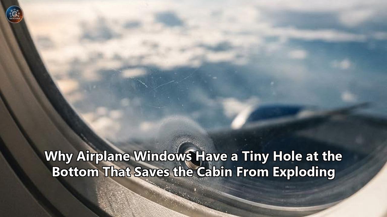
The reason a fractured window at seven miles altitude did not cause a catastrophic failure comes down to a fundamental safety feature that most passengers pass by without a second thought: a microscopic, 3-millimeter hole drilled into the bottom of the acrylic window pane.
This deliberate aperture—known in aerospace engineering as a "bleed hole" or "breather hole"—is not a manufacturing defect or an air vent. It is the visible core of a multi-tiered pressure management system engineered to survive structural failure under extreme atmospheric stress. Examining why airplane windows have holes offers a masterclass in failure containment, load isolation, and passive engineering redundancy.
The Physics of 35,000 Feet: Structural Loads and Pressure Differentials
To understand why a tiny pinhole prevents an airliner from exploding, one must first analyze the physical environment commercial jets inhabit. At a standard cruising altitude of 35,000 to 39,000 feet, an aircraft operates in a domain utterly hostile to human biology. Ambient atmospheric pressure drops to roughly 3.4 to 3.8 pounds per square inch (psi), compared to 14.7 psi at sea level. Outside air temperatures hover around -56°C (-69°F), and oxygen levels are far too sparse to sustain human consciousness.
To keep passengers alive and comfortable without requiring oxygen masks, the aircraft’s environmental control system continuously pumps compressed air into the fuselage. This pressurizes the cabin interior to an equivalent altitude of approximately 6,000 to 8,000 feet above sea level, corresponding to an internal pressure of roughly 11.0 to 12.0 psi.
+-----------------------------------------------------------------------+
|                       CABIN INTERIOR (11.5 psi)                       |
|                                                                       |
|   [Inner Scratch Pane]  [Middle Pane w/ Bleed Hole]   [Outer Pane]    |
|            ||                   ||  o  <--Hole            ||          |
|            ||                   ||                        ||          |
|  Unstressed Dust Shield    Zero Load Reserve      Carries 100% Load   |
|            ||                   ||                        ||          |
+------------||-------------------||------------------------||----------+
                                                      ||
                                              OUTSIDE (3.5 psi)
This creates a significant pressure differential ($\Delta P$) across the aircraft’s skin:
$$\Delta P = P_{\text{cabin}} - P_{\text{outside}} = 11.5\text{ psi} - 3.5\text{ psi} = 8.0\text{ psi}$$
An 8.0 psi difference might sound modest in isolation, but spread over the entire surface area of a jetliner, the cumulative structural force is immense. Consider a standard passenger cabin window measuring approximately 10 inches by 15 inches, yielding a surface area of 150 square inches.
Applying the fundamental equation for mechanical force ($F = P \times A$):
$$F = 8.0\text{ lbs/in}^2 \times 150\text{ in}^2 = 1,200\text{ lbs}$$
Every single window pane lining the cabin wall is subjected to more than half a ton of outward explosive thrust on every single flight. Multiply that figure across the 60 to 100 windows on a commercial airliner, and the internal air pressure is constantly trying to blow the airplane apart like an over-inflated balloon.
If a structural window assembly experiences a sudden, uncontained structural failure at cruising altitude, the pressurized air inside the cabin rushes toward the opening at near-sonic speeds, creating a rapid decompression event capable of tearing away adjacent fuselage panels. Preventing this requires an assembly that can sustain a complete structural failure of its primary glass barrier without losing cabin seal.
Anatomy of a Three-Pane Assembly
Commercial airliner passenger windows are not made of traditional silica glass, which is heavy, brittle, and prone to shattering under cyclic thermal stress. Instead, they are constructed from high-strength stretched acrylic (poly-methyl methacrylate), arranged in a sophisticated three-layer sandwich assembly mounted within an elastomeric rubber seal:
- The Outer Pane (Primary Structural Layer): Positioned on the exterior skin of the aircraft, this layer is constructed from thick, structural-grade stretched acrylic, typically 12 millimeters thick. It is engineered to carry the entire pressure load of the cabin under normal flight conditions.
- The Middle Pane (Fail-Safe Reserve Layer): Situated directly behind the outer pane, separated by a narrow air gap, this layer is slightly thinner (around 6 millimeters). It is made of the same high-strength acrylic but is held in complete structural reserve. It contains the breather hole.
- The Inner Pane (Scratch/Dust Shield): The thin plastic layer that passengers can physically touch. It carries no structural load whatsoever. Its sole purpose is to protect the middle and outer structural panes from human interaction—preventing passengers from scratching the load-bearing acrylic with fingernails, rings, or carry-on luggage.
+-------------------------------------------------------------------------------+
| Layer          | Material          | Structural Role                          |
+----------------+-------------------+------------------------------------------+
| Outer Pane     | Stretched Acrylic | Carries 100% of cabin pressure differential|
| Middle Pane    | Stretched Acrylic | Zero-stress standby; secondary pressure seal|
| Bleed Hole     | Open Aperture     | Equalizes air gap pressure with cabin    |
| Inner Pane     | Polycarbonate     | Sacrificial shield against passenger contact|
+----------------+-------------------+------------------------------------------+
The central dilemma facing aerospace engineers when designing this three-layer sandwich was how to manage structural load distribution.
If both structural panes (outer and middle) were completely sealed without air passage, the trapped air between them would compress and expand unpredictably as the aircraft climbed and descended. Worse, if both panes shared the pressure load equally—say, each bearing 4.0 psi of force—both panes would be subjected to continuous, cyclic material fatigue during every flight cycle. Over thousands of flight hours, microscopic fatigue cracks would propagate through both panes simultaneously. If the outer pane fractured from fatigue, the middle pane behind it would already be compromised and fatigued, vastly increasing the risk of a dual-pane blowout.
To solve this, engineers turned to the principle of Unstressed Standby Redundancy: keeping a backup component in pristine, zero-stress condition so that its structural integrity remains at 100% until the moment the primary component fails. Achieving this required a simple physical mechanism to ensure the middle pane bears no pressure during normal operation.
That mechanism is why airplane windows have holes.
Fluid Mechanics of the Bleed Hole: How Load Isolation Works
The bleed hole is a tiny aperture, roughly 3 to 6 millimeters in diameter, drilled through the lower center of the middle acrylic pane. By providing an unimpeded pathway for air to move between the passenger cabin and the inter-pane air gap, the hole dictates the pressure distribution across the window assembly.
NORMAL FLIGHT CONDITIONS:
Cabin Pressure (11.5 psi) ---> [Bleed Hole] ---> Inter-Pane Gap (11.5 psi)
                                                     |
                                            Outer Pane Bears 8.0 psi
                                                     |
                                                     v
                                          Outside Air (3.5 psi)

Middle Pane Differential:  11.5 psi - 11.5 psi = 0.0 psi (Zero Stress)
Outer Pane Differential:   11.5 psi -  3.5 psi = 8.0 psi (100% Load)
Normal Flight Conditions
As an aircraft climbs to its cruising altitude, cabin pressurization systems pump air into the interior, raising cabin pressure to 11.5 psi. Air from the cabin flows freely through the bleed hole into the small cavity between the middle and outer panes. As a result, the air pressure inside the inter-pane gap ($P_{\text{gap}}$) instantly equalizes with the internal cabin pressure ($P_{\text{cabin}}$):
$$P_{\text{gap}} = P_{\text{cabin}} = 11.5\text{ psi}$$
Now, consider the net pressure differential acting across the middle pane ($\Delta P_{\text{middle}}$):
$$\Delta P_{\text{middle}} = P_{\text{cabin}} - P_{\text{gap}} = 11.5\text{ psi} - 11.5\text{ psi} = 0.0\text{ psi}$$
Because the air pressure is identical on both sides of the middle pane, it experiences zero physical force. It rests in the window frame completely unbent, uncompressed, and unfatigued, floating in pressure equilibrium.
Meanwhile, consider the pressure differential acting across the outer pane ($\Delta P_{\text{outer}}$):
$$\Delta P_{\text{outer}} = P_{\text{gap}} - P_{\text{outside}} = 11.5\text{ psi} - 3.5\text{ psi} = 8.0\text{ psi}$$
The outer pane carries 100% of the aircraft’s cabin pressure load entirely on its own. It absorbs the cyclic expansion and contraction of every takeoff and landing, keeping the middle pane completely insulated from flight-induced material degradation.
OUTER PANE FAILURE INCIDENT (e.g., United Flight 108):
Outer Pane Fractures ---> Air in Gap Escapes Outward ---> Gap Pressure Drops (3.5 psi)
                                                                |
Cabin Pressure (11.5 psi) ===> [Bleed Hole Restricts Airflow] ===> Gap
                                                                |
                                                  Middle Pane Instantly Engages!
                                                  Differential: 11.5 - 3.5 = 8.0 psi
Outer Pane Structural Failure (The Case Study Dynamics)
When an outer pane fractures mid-flight—as occurred on United Flight 108—the mechanics invert instantly:
- Primary Structural Breach: The cracked outer pane loses its structural boundary, allowing the pressurized air trapped inside the inter-pane gap to vent out into the thin atmosphere.
- Choked Flow Rate Limiting: Pressurized cabin air tries to rush through the middle pane to fill the escaping void. However, because the bleed hole is only 3 millimeters wide, it acts as an orifice flow restrictor, drastically throttling the volumetric flow rate of air passing through. Air cannot bleed out of the cabin fast enough to cause a sudden drop in cabin pressure.
- Secondary Engagement: The pressure inside the inter-pane gap drops rapidly toward the external atmospheric pressure ($P_{\text{gap}} \to 3.5\text{ psi}$). Within milliseconds, a large pressure differential forms across the middle pane:
$$\Delta P_{\text{middle}} = P_{\text{cabin}} - P_{\text{gap}} = 11.5\text{ psi} - 3.5\text{ psi} = 8.0\text{ psi}$$
- Immediate Containment: The middle pane—having sat for thousands of flight hours in zero-stress reserve—takes over 100% of the structural load instantly. Because it has suffered zero cyclic fatigue, its full structural capacity is available to hold back the cabin air.
The cabin seal remains entirely intact. The pilots receive a routine structural alert, descend the aircraft to a lower altitude where ambient air is breathable, and divert safely to an airport—turning what could have been an explosive emergency into a minor flight delay.
Moisture Mitigation and Thermal Dynamics: The Secondary Function
While structural safety and load isolation are the primary life-saving reasons why airplane windows have holes, the aperture serves a vital secondary purpose: environmental moisture management and fog mitigation.
At a cruising altitude of 35,000 feet, the exterior surface of the outer acrylic pane is exposed to outside temperatures as low as -56°C (-69°F). At the same time, the interior surface of the innermost pane is exposed to a cabin maintained at a comfortable +21°C (+70°F). This creates a severe temperature gradient across a window assembly that spans less than two inches in depth.
       INSIDE CABIN (+21°C / Warm & Humid)
                       |
                       v
            [Inner Scratch Shield]
                       |
                       v
            [Middle Pane w/ Bleed Hole]  <--- Dry cabin air vents slowly
                       |                      through, purging moisture.
                       v
            [Inter-Pane Air Gap]         <--- Dew point maintained below -50°C
                       |                      No fogging or ice formation!
                       v
             [Outer Acrylic Pane]
                       |
                       v
       OUTSIDE ATMOSPHERE (-56°C / Extreme Cold)
Human occupants release substantial amounts of moisture into cabin air through respiration and perspiration. A standard commercial aircraft carrying 200 passengers generates several gallons of water vapor in flight. If the air gap between the outer and middle window panes were hermetically sealed at ground level on a humid afternoon, that moisture would remain trapped inside the gap.
When the plane climbed into freezing air, the temperature of the outer acrylic pane would drop below the dew point of the trapped air. Moisture would condense onto the inside surface of the outer glass, forming thick frost, ice, or persistent fog.
This creates three major operational hazards:
- Loss of Visual Inspection Capability: Flight crews use passenger windows to perform visual inspections of aircraft wings, engines, control surfaces, and fuel vents during unexpected inflight anomalies. Opaque, frosted windows prevent visual damage verification.
- Material Degradation: Trapped water pooling inside the window frame causes corrosion of aluminum mounting retainers and accelerates breakdown of elastomeric rubber seals.
- Ice Expansion Stress: Freezing water expands, exerting localized mechanical pressure against the edges of the acrylic panes that can induce stress fractures over time.
The bleed hole solves this through continuous, passive air purging. As the aircraft climbs and cabin pressure drops slightly, air bleeds out of the gap. As the aircraft descends, dry air from the cabin’s environmental control system—which constantly filters and dehumidifies air—cycles back into the gap.
This continuous micro-venting ensures the relative humidity within the inter-pane cavity remains near zero, keeping the dew point below the external temperature. Passengers enjoy a clear, unobstructed view of the sky, and maintenance crews can visually inspect the aircraft skin at any time.
Written in Blood: The Historical Evolution of Aircraft Windows
The elegant physics of modern aircraft windows did not emerge overnight; it was forged through tragic lessons in the early years of high-altitude commercial flight.
In the late 1940s, British aviation manufacturer De Havilland introduced the world’s first commercial jetliner, the Comet. Flying twice as fast and twice as high as propeller-driven predecessors, the Comet featured a pressurized cabin and large, stylish square windows.
In 1954, two De Havilland Comet aircraft—Flight 781 and Flight 201—suffered catastrophic mid-air breakups at high altitude, plunging into the Mediterranean Sea with the loss of all passengers and crew.
SQUARE WINDOW GEOMETRY (1950s Comet - FAILED)
+-------------------+
|                   |   <-- 90° Sharp Corners
|     WINDOW        |   <-- Cyclic stress concentrates at corners!
|                   |   <-- Micro-cracks propagate outward.
+-------------------+   RESULT: Catastrophic Fuselage Breakup.

ROUNDED WINDOW GEOMETRY (Modern Jetliners - SAFE)
   /------------- \
  /                \  <-- Continuous curved geometry
 |      WINDOW      | <-- Pressure stress distributes evenly!
  \                /  <-- No sharp inflection points.
   \--------------/   RESULT: Structural loads absorbed safely.
The resulting investigation, led by Sir Arnold Hall at the Royal Aircraft Establishment in Farnborough, involved constructing a giant water tank capable of submerging an entire Comet fuselage. Investigators pumped water into and out of the cabin to simulate thousands of flight pressurization cycles.
The investigation uncovered two revolutionary insights that reshaped aerospace safety forever:
- Stress Concentration Around Sharp Corners: When a structure is pressurized, internal force spreads evenly along smooth curves. When an opening cut into the fuselage skin features sharp 90-degree corners—like the Comet’s square windows—the structural stress accumulates disproportionately at those corner points. Cyclic pressurization caused metal fatigue to concentrate at the window corners, giving rise to microscopic cracks that ripped open the fuselage like a zipper.
- Single-Barrier Vulnerability: Early aircraft windows relied on single structural panes without redundant standby layers or controlled pressure-bleeding mechanisms. If a pane cracked, total pressure loss was instantaneous.
Following the Comet investigation, international airworthiness regulations mandated two major architectural changes for all commercial aircraft:
- Mandatory Curved Geometry: Windows were required to feature rounded, oval, or circular shapes, completely eliminating sharp corners and distributing pressurization forces evenly along the structural frame.
- Multi-Layer Fail-Safe Redundancy: Aircraft windows had to feature multi-pane assemblies with isolated pressure loads, ensuring that no single material failure could breach the overall cabin structure.
+---------------------------------------------------------------------------------------+
| Historical Event               | Root Cause of Failure    | Engineering Paradigm Shift|
+--------------------------------+--------------------------+---------------------------+
| De Havilland Comet (1954)      | Stress concentration at  | Mandated round windows    |
|                                | square window corners    | and curved geometry       |
+--------------------------------+--------------------------+---------------------------+
| British Airways 5390 (1990)    | Incorrect bolt sizes     | Overhaul of maintenance   |
|                                | on cockpit windshield    | retention fastener rules  |
+--------------------------------+--------------------------+---------------------------+
| Southwest Airlines 1380 (2018) | Engine shrapnel broke    | Enhanced engine casing    |
|                                | both window panes        | containment shields       |
+--------------------------------+--------------------------+---------------------------+
| United Flight 108 (2026)       | Outer pane crack; middle | Validation of modern      |
|                                | pane held via bleed hole | bleed hole fail-safe design|
+--------------------------------+--------------------------+---------------------------+
The effectiveness of this paradigm was demonstrated during a May 2018 incident involving Southwest Airlines Flight 957. Cruising from Chicago to Newark, passengers were alarmed when an outer window pane suddenly shattered into a web of cracks. Because the middle pane remained unfatigued and insulated from stress by its bleed hole, the window held firm. The aircraft diverted to Cleveland without declaring an emergency, and cabin pressure remained completely stable throughout the landing.
Contrast this with the tragedy of Southwest Airlines Flight 1380 just two weeks prior, where an uncontained engine explosion hurled high-velocity titanium fan blade shrapnel directly into a window assembly. In that extreme instance, the kinetic impact physically destroyed both the outer and middle panes simultaneously, bypassing the fail-safe system and triggering a rapid decompression.
The lesson was clear: multi-pane window assemblies with bleed holes provide complete protection against atmospheric pressure differential failures and material fatigue, though extreme kinetic impacts from external shrapnel require additional containment layers around engine housings.
Core Principles for Industrial and Systems Engineering
The humble bleed hole provides an extraordinary case study in engineering design. The underlying mechanisms that make this 3-millimeter aperture so effective translate directly into core engineering principles across software design, mechanical engineering, structural architecture, and civil infrastructure.
                  =============================================
                  CORE ENGINEERING PRINCIPLES OF THE BLEED HOLE
                  =============================================

        +-------------------------------------------------------+
        | 1. Unstressed Standby Redundancy                      |
        |    Keep backup components isolated from daily stress  |
        |    so they remain at 100% health when primary fails.  |
        +-------------------------------------------------------+
                                    |
        +-------------------------------------------------------+
        | 2. Passive Systems Over Active Controls               |
        |    Eliminate moving parts, sensors, and software;     |
        |    rely purely on basic laws of fluid mechanics.      |
        +-------------------------------------------------------+
                                    |
        +-------------------------------------------------------+
        | 3. Choked Flow-Rate Limiting                          |
        |    Use physical geometry apertures to throttle asset  |
        |    loss during primary boundary breaches.            |
        +-------------------------------------------------------+
                                    |
        +-------------------------------------------------------+
        | 4. Sacrificial Defensive Layering                     |
        |    Protect costly core infrastructure with cheap,     |
        |    easily replaceable outer components.               |
        +-------------------------------------------------------+
1. Unstressed Standby Redundancy
In high-reliability systems engineering, running two redundant components in parallel load-sharing mode is often a hidden trap. If a primary server, power transformer, or bridge support beam carries 50% of the daily operational load alongside a secondary component, both components degrade, wear out, and accumulate fatigue at the exact same rate. When the primary fails, the backup is already severely worn and highly likely to fail shortly thereafter.
The bleed hole demonstrates why airplane windows have holes: to decouple the backup layer entirely from operational stress. By allowing air pressure to equalize across the middle pane, engineers ensure the backup component sits at zero stress until primary failure occurs.
In cloud computing architectures, this equates to Active-Passive Failover with Isolated Load: passive standby databases must not process query load or share write queues during routine ops, ensuring their hardware state and index structures remain pristine for emergency takeover.
2. Passive Safety Mechanisms vs. Active Controls
An active safety system relies on sensors to detect a problem, microprocessors to compute a response, and electromechanical actuators to trigger a defensive action. If sensors lose power, software encounters a bug, or an actuator freezes, the safety system fails.
The bleed hole is a purely passive safety mechanism. It features no moving parts, requires no electrical power, uses no digital code, and demands no human intervention. It relies solely on the immutable laws of fluid dynamics. When primary structural failure occurs, the change in pressure differential forces the system into its fail-safe state automatically and instantaneously.
Engineers should always prioritize passive, geometry-driven physical solutions over complex digital control loops for mission-critical safety boundaries.
3. Choked Flow-Rate Limiting
When a system boundary is breached, the rate of loss dictates whether the incident is a manageable event or a catastrophic failure. The small physical dimension of the bleed hole acts as an orifice flow limiter. It allows micro-volumes of air to pass slowly during altitude changes, but restricts large volumes of air during a blowout.
In cybersecurity and microservices architecture, this concept translates to Aperture Rate Limiting. API gateways should be designed with tight, physically restricted throughput limits between trust zones. If a breach occurs inside a microservice, restricted data transfer apertures prevent mass exfiltration of sensitive records, granting automated monitoring systems time to isolate the affected node.
4. Sacrificial Layering
The non-structural inner pane protects the load-bearing middle and outer acrylic panes from routine passenger contact. It is cheap, easy to manufacture, and quickly replaced during standard maintenance gate turns.
Industrial designs should always incorporate low-cost, sacrificial outer layers to shield high-value, hard-to-replace structural cores from unpredictable user environments.
Smart Glass and Modern Cabin Evolution
As commercial aviation advances, the physical architecture of cabin windows continues to evolve. Modern widebody aircraft like the Boeing 787 Dreamliner, Airbus A350, and Boeing 777X feature cabin windows up to 65% larger than traditional airliners, offering expansive panoramic views and brighter cabin interiors.
                  MODERN SMART-GLASS WINDOW ASSEMBLY

[Inner Sacrificial] ---> [Electrochromic Gel Layer] ---> [Middle Pane w/ Bleed Hole] ---> [Outer Pane]
   (Polycarbonate)        (Dimmable Smart Glass)              (Acrylic Reserve)          (Acrylic Load)
These modern airliners have largely eliminated traditional pull-down plastic shades in favor of Electrochromic Smart-Glass Windows. These systems use an electrochromic gel layer sandwiched between thin conductive panels. When flight attendants or passengers adjust the tint controls, a low-voltage electrical current passes through the gel, altering its molecular structure to absorb light and darkening the window from fully transparent to deep night-blue.
Despite this integration of advanced electronics and materials science, the fundamental structural challenge remains identical: the pressurized cabin must still be held back from the thin atmosphere outside.
Because smart-glass modules cannot alter the basic laws of atmospheric fluid dynamics, electrochromic window units on airliners still incorporate multi-pane acrylic air gaps and physical breather holes. The smart-glass tinting layers are housed within the inner glass assemblies, while the primary load-bearing outer pane and the zero-stress middle pane—complete with its life-saving bleed hole—continue to perform their protective role silently in the background.
Looking ahead, aerospace researchers are developing next-generation structural health monitoring (SHM) systems for commercial window assemblies. By embedding fiber-optic acoustic emission sensors into the elastomeric rubber seals surrounding window frames, avionics computers can detect microscopic micro-cracks developing inside outer acrylic panes hundreds of flight hours before they become visible to the human eye.
Yet, even as artificial intelligence and advanced sensor networks reshape aircraft maintenance, the primary defense against mid-flight decompression will remain an elegantly simple physical feature: a 3-millimeter pinhole drilled into a sheet of plastic acrylic, silently equalizing pressure seven miles above the earth.
Reference:
- https://www.wusa9.com/article/travel/flights/cracked-plane-windshield-dulles-flight-divert-to-boston/65-0223f34e-1521-42a8-a641-ef3d43ed9ba5
- https://www.9news.com/article/news/why-southwests-cracked-window-wasnt-as-scary-as-it-looked/73-548172339
- https://okdiario.com/techy/en/a-pilot-reveals-the-hidden-hole-in-airplane-windows-and-the-reason-it-exists-is-more-serious-than-most-passengers-imagine/4502/
- https://www.youtube.com/watch?v=aKrNjmDnLM4
- https://blog.monroeaerospace.com/whats-the-deal-with-the-small-holes-in-airplane-windows/
- https://www.youtube.com/watch?v=wz7vuOs3s94
- https://www.youtube.com/watch?v=nfG9wxwU5iw