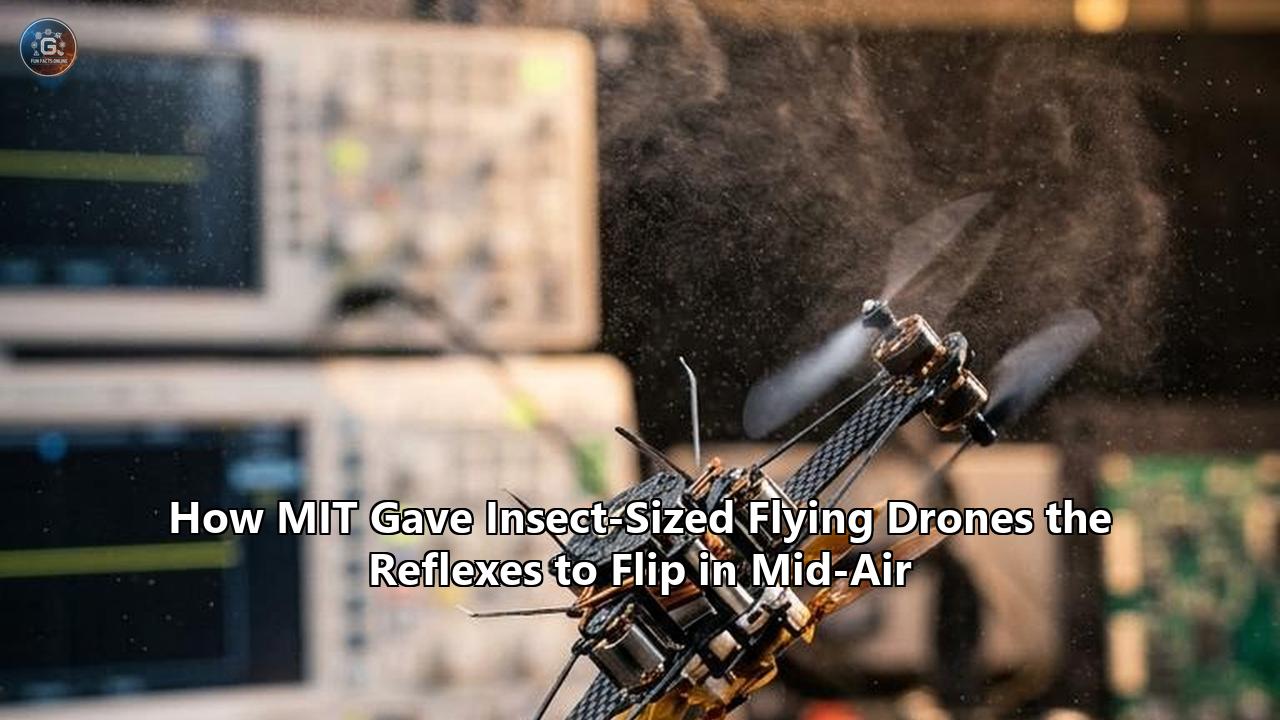
Inside a high-ceilinged flight cage on the fourth floor of MIT’s Research Laboratory of Electronics, a carbon-fiber insect weighing less than a single raisin just accomplished what many roboticists considered impossible for two decades.
Measuring barely four centimeters from wingtip to wingtip and weighing just 750 milligrams, the micro-aerial vehicle lifted off, accelerated laterally across the enclosure, pitched violently backward into pure verticality, and executed a complete 360-degree somersault. It did not tumble out of the air. It did not drift off course. Instead, it arrested its rotational momentum within milliseconds, leveled off, and repeated the maneuver nine more times in rapid succession, completing ten continuous flips in 11 seconds while never deviating more than five centimeters from its planned trajectory.
The demonstration, detailed in Science Advances by a joint research team from MIT’s Soft and Micro Robotics Laboratory and the Aerospace Controls Laboratory, marks an unprecedented leap in microrobotic performance. Led by Associate Professor Kevin Yufeng Chen and Ford Professor of Engineering Jonathan P. How, alongside co-lead authors Yi-Hsuan Hsiao, Andrea Tagliabue, and Owen Matteson, the researchers unlocked flight mechanics once restricted to biological dipterans.
The robot, known internally as SoftFly, achieved lateral speeds of 197 centimeters per second and lateral accelerations of 11.7 meters per square second—representing gains of 447 percent and 255 percent, respectively, over the team's prior best demonstrations. During testing, it repeatedly executed aggressive insect "saccades"—violent, sharp turns followed by immediate reverse-pitch braking—even when struck by 160-centimeter-per-second artificial wind gusts.
The headlines covering the research celebrated a drone that can do backflips. Yet behind the laboratory doors, the actual breakthrough is far more consequential than a gymanstic party trick. The MIT team solved an insidious physical and mathematical paradox: at the millimeter scale, the physics of flight are violently unforgiving, and the computational power required to prevent catastrophic crashes vastly exceeds what any insect-scale flyer can carry.
By pairing damage-tolerant soft artificial muscles with a deep-learned robust tube model predictive control architecture, the team created a synthetic neuromuscular reflex loop. The architecture allows insect-sized flying drones to compute optimal, aerodynamically extreme trajectories at millisecond latencies, bypassing the linear control limits that have paralyzed the field for a generation.
The Physics Trap at the Sub-Gram Boundary
To understand why a micro-drone executing a clean somersault is an extraordinary engineering feat, one must first look at the scaling laws that turn classical aerodynamics into a mechanical minefield.
When an engineer shrinks an aerial vehicle down from the scale of a consumer quadcopter to the scale of a honeybee, the physical environment changes character entirely. Quadcopters operate in a high Reynolds number regime ($Re > 10^5$), where inertial forces dominate and air behaves like a predictable, inviscid fluid. A conventional four-rotor drone generates steady aerodynamic lift across rigid, spinning airfoils. Its rotational inertia is high enough that an onboard microcontroller updating at a leisurely 100 to 400 hertz has ample time to sense an angular perturbation, run a simple Proportional-Integral-Derivative (PID) algorithm, and adjust motor RPM before the vehicle capsizes.
SCALING MISMATCH AT THE SUB-GRAM BOUNDARY:
══════════════════════════════════════════════════════════════
Physical Metric        Macro Scale (Quadcopters)    Micro Scale (Insects / SoftFly)
──────────────────────────────────────────────────────────────
Characteristic Size    20 cm to 100 cm              1 cm to 4 cm
Mass                   500 g to 2,000 g             0.5 g to 1.0 g
Reynolds Number (Re)   100,000 to 500,000           100 to 1,000
Fluid Regime           Inertial, predictable        Viscous, dynamic stall
Rotational Inertia (I) Scales with L⁵ (High)        Scales with L⁵ (Extremely Low)
Aerodynamic Damping    Scales with L⁴ (Moderate)    Scales with L⁴ (Dominant)
Rotational Rates       100° to 300° / sec           Exceeding 5,000° / sec
Flapping Frequency     N/A (Continuous rotary)      300 Hz to 500 Hz
Instability Timescale  100 to 200 milliseconds      10 to 20 milliseconds
Control Latency Limit  Low (< 50 Hz acceptable)     High (> 500 Hz critical)
══════════════════════════════════════════════════════════════
Shrink that vehicle down to sub-gram proportions, and physics revolts. At dimensions under five centimeters, the Reynolds number plunges into the viscous regime ($Re \approx 10^2 - 10^3$). Continuous rotary motors fail; micro-scale electric motors suffer catastrophic efficiency loss due to thermal dissipation in microscopic copper windings, magnetic flux leakage, and surface friction in micro-bearings that quickly overpowers torque output.
Consequently, micro-flyers must rely on flapping wings to generate unsteady lift mechanisms: leading-edge vortex (LEV) generation, delayed stall, and rapid wake capture.
The far greater challenge lies in rotational inertia. Inertia scales with the fifth power of characteristic length ($I \propto L^5$), whereas aerodynamic damping scales with the fourth power ($D \propto L^4$). As an aerial robot shrinks, its resistance to rotation drops exponentially faster than the aerodynamic damping forces resisting that motion.
A sub-gram flyer possesses virtually zero rotational inertia. If a sudden draft, an uneven wing stroke, or an aerodynamic wake disturbance induces an uncommanded torque, the flyer does not drift or gently roll. It enters an uncontrollable tumble at rotational velocities exceeding several thousand degrees per second.
THE MILLISECOND WINDOW OF DIVERGENCE:
┌──────────────────────────────────────────────────────────────┐
│ Wingbeat Period: ~2.0 to 2.5 ms (flapping at 400–500 Hz)     │
└──────────────┬───────────────────────────────────────────────┘
               │
               ▼
┌──────────────────────────────────────────────────────────────┐
│ External Disturbance / Asymmetric Stroke (t = 0 ms)          │
└──────────────┬───────────────────────────────────────────────┘
               │
               ▼
┌──────────────────────────────────────────────────────────────┐
│ Angular Acceleration Sparks Rotational Runaway (> 5,000°/s)   │
└──────────────┬───────────────────────────────────────────────┘
               │
               ▼
┌──────────────────────────────────────────────────────────────┐
│ The Critical Instability Threshold (t = 15 to 20 ms)         │
│   • Linear controller assumption collapses                   │
│   • Attitude diverges past recovery envelope                 │
│   • Actuator saturation causes unrecoverable crash           │
└──────────────────────────────────────────────────────────────┘
An uncorrected attitude error will cause total catastrophic flight divergence within 15 to 20 milliseconds. That is roughly the duration of five to eight wingbeats.
For the past twenty years, tiny robots attempting acrobatic maneuvers hit a mathematical wall. If an engineer wanted a micro-vehicle to flip, the craft had to pitch past 90 degrees. But as soon as its attitude shifted beyond small-angle assumptions, the linear control systems governing the vehicle collapsed. The robot entered highly nonlinear aerodynamic regions where downward lift momentarily inverted into upward drag, the vehicle's own shed vortices struck its airframe, and the machine plummeted out of the air.
Biological flies execute these violent maneuvers effortlessly because their nervous systems do not rely on slow, deliberative reasoning. They blend biomechanical pre-flexes with dedicated motor neuron arcs that respond to sensory cues in fractions of a wingbeat. Replicating that balance of physical robustness and lightning-fast reflex required MIT to rethink both the muscles driving the wings and the mathematical brain computing their motion.
The Muscle Engine: Dielectric Elastomer Actuators
Before the control team could write a single line of flight code, they needed an airframe capable of surviving violent acrobatics without shattering.
For more than a decade, the gold standard in sub-gram micro-aerial robotics was Harvard University's pioneering RoboBee. Built using folded carbon-fiber origami and powered by piezoelectric ceramic actuators—specifically lead zirconate titanate (PZT) bimorphs—the RoboBee was an astonishing demonstration of micro-scale manufacturing. Yet PZT bimorphs possess a critical, unforgiving flaw: brittle ceramics have a tensile fracture strength of only 120 megapascals and a failure strain limit of just 0.3 percent.
If a ceramic-driven microrobot strikes a wall, brushes against an obstacle, or encounters aggressive turbulence that forces its wings beyond their deflection envelope, the actuator snaps like an uncooked strand of spaghetti. Biological bumblebees collide with vegetation and obstacles roughly once every second while foraging, relying on soft, flexible body structures to absorb the shock and maintain flight. A brittle flyer made of piezoelectric crystals could never achieve real-world acrobatics because a single mistimed maneuver or minor collision meant physical destruction.
ACTUATOR ARCHITECTURE COMPARISON:
══════════════════════════════════════════════════════════════
Parameter               Piezoelectric Ceramics (PZT)  Dielectric Elastomers (DEA)
──────────────────────────────────────────────────────────────
Material Nature         Brittle crystal / piezoceramic Compliant elastomer / polymer
Failure Strain Limit    0.3%                          > 100% (elastomeric limit)
Tensile Fracture Limit  ~120 MPa                      Resilient / soft matrix
Power Density           ~1.0 kW/kg                    1.2 kW/kg
Operating Voltage       100 V to 300 V                1,000 V to 2,000 V
Damage Resilience       Shatters on impact            Absorbs collisions / self-clearing
Operating Frequency     150 Hz to 250 Hz              400 Hz to 500 Hz
Mechanical Lifespan     Fatigue-prone flexures        Demonstrated > 1,000 seconds
══════════════════════════════════════════════════════════════
Chen’s laboratory abandoned piezoelectric ceramics entirely, pioneering the use of high-power-density Dielectric Elastomer Actuators (DEAs) for sub-gram flight.
A DEA is an artificial muscle constructed from an ultra-thin elastomeric cylinder or multi-layered polymer core sandwiched between compliant conductive electrodes made of carbon nanotubes (CNTs). The operating mechanism is governed by electrostatic Maxwell stress:
$$\sigma_M = \epsilon_0 \epsilon_r E^2 = \epsilon_0 \epsilon_r \left(\frac{V}{d}\right)^2$$
Where $\epsilon_0$ is the vacuum permittivity, $\epsilon_r$ is the relative dielectric constant of the elastomer, $E$ is the applied electric field, $V$ is the applied voltage, and $d$ is the thickness of the dielectric layer.
DIELECTRIC ELASTOMER ACTUATION MECHANICS:
               Carbon Nanotube (CNT) Electrode (+)
  ┌────────────────────────────────────────────────────────┐
  │ ▲   ▲   ▲   ▲   ▲   ▲   ▲   ▲   ▲   ▲   ▲   ▲   ▲   ▲  │
  ├─┼───┼───┼───┼───┼───┼───┼───┼───┼───┼───┼───┼───┼───┼──┤
  │ │   │   │   │   Maxwell Stress (σ_M)│   │   │   │   │  │
  │ ▼   ▼   ▼   ▼   Compresses Thickness▼   ▼   ▼   ▼   ▼  │
  │                                                        │ ──► Longitudinal
  │              Dielectric Elastomer Core                 │     Expansion
  │                                                        │ ──► Along Axis
  │ ▲   ▲   ▲   ▲   ▲   ▲   ▲   ▲   ▲   ▲   ▲   ▲   ▲   ▲  │
  ├─┼───┼───┼───┼───┼───┼───┼───┼───┼───┼───┼───┼───┼───┼──┤
  │ ▼   ▼   ▼   ▼   ▼   ▼   ▼   ▼   ▼   ▼   ▼   ▼   ▼   ▼  │
  └────────────────────────────────────────────────────────┘
               Carbon Nanotube (CNT) Electrode (-)
When high voltage (typically between 1,000 and 2,000 volts) is applied across the carbon nanotube layers, opposing electrostatic charges accumulate on the electrodes. The resulting Maxwell stress squeezes the elastomer cylinder in the thickness direction. Because the elastomer is virtually incompressible (Poisson's ratio $\nu \approx 0.5$), this transverse compression forces the actuator to expand axially along its length. When the voltage drops to zero, the material's elastic restoring forces instantly snap it back to its resting state.
By alternating this kilovolt signal at frequencies up to 500 hertz, the actuator acts as a high-frequency linear motor.
Building these actuators is an exercise in extreme micro-fabrication. In Chen's lab, researchers roll dielectric elastomer films down to thicknesses under 10 micrometers. A single airborne dust particle trapped between the elastomer and the carbon nanotube coat will create a local dielectric breakdown point: an electric arc that punches a microscopic hole through the film, vaporizes the electrode, and shorts the entire actuator.
To overcome this, Chen's group perfected a self-clearing manufacturing process. If a localized breakdown occurs, the micro-arc vaporizes the ultra-thin carbon nanotube layer immediately surrounding the fault, insulating the defect and allowing the artificial muscle to continue functioning—a synthetic analog to biological tissue scarification.
A micro-machined carbon-fiber four-bar transmission mechanism connects each DEA to an ultra-lightweight wing made of a carbon-fiber frame supporting a 1.5-micrometer-thick mylar membrane. The transmission magnifies the minute linear displacement of the DEA into a flapping stroke amplitude exceeding 100 degrees.
In the 750-milligram SoftFly configuration used for the aerobatic trials, four independent DEAs drive four separate wings arranged in an X-configuration. This quad-actuator layout gives the vehicle four distinct control inputs ($u_1, u_2, u_3, u_4$). By modulating the peak voltage and driving frequency of each actuator independently, the robot generates differential lift forces and aerodynamic torques across three axes:
- Roll Torque ($\tau_x$): Produced by driving the left-side actuators at higher voltages than the right-side actuators.
- Pitch Torque ($\tau_y$): Produced by creating a voltage differential between the anterior (front) and posterior (rear) actuators.
- Yaw Torque ($\tau_z$): Generated by split-cycle asymmetry—modulating the shape of the voltage waveform between upstroke and downstroke, altering the wing's drag profile during stroke reversal.
In earlier iterations, soft micro-flyers lacked durability; off-axis torsional strain rapidly destroyed the mechanical joints connecting the soft muscle to the rigid carbon transmission.
In research leading up to the acrobatic flights, Chen's team redesigned the hinge geometry with multi-layer polyimide flexures that eliminated off-axis torsional twisting. The mechanical lifespan of the soft actuator surged from less than 10 seconds to more than 1,000 seconds of continuous hover—providing the structural resilience required to endure repetitive, high-g somersault maneuvers.
The hardware was finally robust enough to flip. But the mathematical problem of controlling that flip remained unsolved.
Why Conventional Controllers Failed
Until recently, flight control for micro-aerial vehicles was dominated by classical linear control theory.
Engineers implemented Cascaded PID (Proportional-Integral-Derivative) loops or Linear Quadratic Regulators (LQR). These controllers operate under a fundamental assumption: that the dynamics of the vehicle can be linearized around a stable, stationary hovering equilibrium point.
THE LIMITS OF LINEAR CONTROL THEORY IN ACROBATIC FLIGHT:
──────────────────────────────────────────────────────────────
Hover Assumption:          Pitch angle θ ≈ 0
Small-Angle Approximation: sin(θ) ≈ θ,  cos(θ) ≈ 1

The Acrobatic Breakdown:   During a somersault, pitch angle θ reaches 90°, 180°, 270°, 360°
                           At θ = 90°:
                           • Nominal vertical lift vector becomes horizontal thrust
                           • Gravity is completely uncompensated along the body z-axis
                           • Cross-axis aerodynamic coupling terms explode
                           • Linear controller assumes error is small and commands wrong inputs
                           • RESULT: Actuator saturation, tumbling, structural divergence
──────────────────────────────────────────────────────────────
Under hover conditions, pitch angle $\theta$ and roll angle $\phi$ are assumed to be near zero, allowing the simplification $\sin\theta \approx \theta$ and $\cos\theta \approx 1$.
In a gentle drift or slow hovering flight, this math holds. But if you command the robot to execute a somersault, the pitch angle sweeps through 90, 180, 270, and 360 degrees. At 90 degrees, the vehicle is perpendicular to the floor: the thrust that previously counteracted gravity now drives the drone horizontally, while gravity acts along what the controller thinks is the lateral body axis.
The cross-coupling dynamics between the aerodynamic forces of the four flapping wings, body angular rates, and wake interactions explode into extreme nonlinearity:
$$\mathbf{M} \dot{\boldsymbol{\nu}} + \mathbf{C}(\boldsymbol{\nu})\boldsymbol{\nu} + \mathbf{g}(\boldsymbol{\eta}) = \boldsymbol{\tau}_{\text{aero}}(V_1, V_2, V_3, V_4, \boldsymbol{\nu}) + \boldsymbol{\tau}_{\text{dist}}$$
Where $\mathbf{M}$ is the mass-inertia matrix, $\mathbf{C}$ is the Coriolis-centripetal matrix, $\mathbf{g}$ is the nonlinear gravitational vector dependent on orientation $\boldsymbol{\eta}$, $\boldsymbol{\tau}_{\text{aero}}$ represents the unsteady aerodynamic forces generated by the actuators at voltages $V_i$ under body velocity $\boldsymbol{\nu}$, and $\boldsymbol{\tau}_{\text{dist}}$ accounts for ambient aerodynamic disturbances and wake ingestion.
When an engineer pushes a linear PID controller into this regime, the system suffers actuator saturation.
The controller observes an enormous tracking error and commands maximum voltage to the actuators. But the actuators have hard physical constraints. Exceed 2,000 volts, and the dielectric elastomer suffers electrical breakdown, turning the muscle into carbon ash. Conversely, command zero volts, and the actuator loses all control authority, causing the wing to flutter passively.
Linear controllers have no native mechanism to anticipate these actuator limits while planning through highly coupled, multivariable flight envelopes.
Furthermore, human trial-and-error manual tuning—the method previously used to find stable gain parameters for sub-gram hovering—proved completely ineffective for dynamic maneuvers. Adjusting gains by hand to make a robot fly smoothly in a horizontal line cannot prepare the system for the transient fluid dynamics of an inverted stall. Every manual adjustment to solve pitch divergence inadvertently introduced roll instabilities or catastrophic yaw spinning.
To break the boundary, the researchers needed an optimization framework that could solve the exact nonlinear physics in advance while enforcing strict physical actuator boundaries. That tool exists in optimal control theory: Model Predictive Control.
Yet Model Predictive Control carried its own fatal computational flaw.
The Algorithmic Breakthrough: Deep-Learned Robust Tube MPC
Model Predictive Control (MPC) is an advanced method of process control that relies on a dynamic mathematical model of the system.
At each sampling step, an MPC algorithm looks ahead into a finite time horizon, solves an open-loop optimal control problem balancing desired trajectory tracking against control effort, and computes the ideal sequence of control inputs while strictly obeying system constraints (such as voltage and torque limits). It executes the first step of the sequence, measures the new state of the robot, and repeats the optimization.
To handle real-world flight, simple MPC is not enough. You need Robust Tube MPC.
THE ROBUST TUBE MODEL PREDICTIVE CONTROL CONCEPT:
══════════════════════════════════════════════════════════════
               Upper Constraint Bound (Actuator Voltage Limit)
- - - - - - - - - - - - - - - - - - - - - - - - - - - - - - -
      ╭──────────────────────────────────────────────────╮
     │   Robust Invariant Error Tube: S(t)                │
     │   ┌──────────────────────────────────────────────┐ │
     │   │      Nominal Planned Trajectory: z*(t)       │ │
────┼───┼──────────────────────────────────────────────┼─┼────► Time
     │   │                                              │ │
     │   │  Actual Disturbed State: x(t)                │ │
     │   │  (Kept strictly inside tube by ancilliary    │ │
     │   │   feedback controller despite wind gusts)    │ │
     │   └──────────────────────────────────────────────┘ │
      ╰──────────────────────────────────────────────────╯
- - - - - - - - - - - - - - - - - - - - - - - - - - - - - - -
               Lower Constraint Bound (Minimum Control Authority)
══════════════════════════════════════════════════════════════
In Robust Tube MPC, the state space is separated into two components: a nominal system trajectory and an error system that captures external disturbances, model inaccuracies, and aerodynamic wake turbulence.
The algorithm computes a central nominal path, $z^(t)$, using an idealized model, and builds a geometric "tube" around that path—a robust positively invariant set, $\mathbb{S}$. The mathematical guarantee of Tube MPC is that as long as the disturbance $\mathbf{w}(t)$ remains bounded within a known set $\mathbb{W}$, the actual system state $\mathbf{x}(t)$ will never escape the cross-sectional walls of the tube:
$$\mathbf{x}(t) \in z^(t) \oplus \mathbb{S}, \quad \forall t \ge 0$$
Crucially, the constraints on actuator voltage, wing stroke amplitude, and structural loads are tightened inward by the exact dimensions of the tube. This mathematically ensures that even if a maximum-intensity wind gust strikes the robot while it is inverted, the feedback response will never command a voltage higher than the physical breakdown threshold of the dielectric elastomer.
The Real-Time Computational Bottleneck
The problem with Robust Tube MPC is computational intensity.
Solving the constrained optimization problem—calculating min-max quadratic programming matrices while optimizing reachable sets over a lookahead horizon—requires immense processor power. On a high-performance desktop workstation, an advanced Tube MPC solver takes between 50 milliseconds and several hundred milliseconds to compute a single control update.
Recall the sub-gram scaling physics: an insect-sized flying drone experiences rotational divergence in under 20 milliseconds. If the controller takes 100 milliseconds to calculate an optimal response, the robot has already flipped into the floor, crashed, and shattered long before the calculation finishes.
To bridge this gap, Jonathan How and Kevin Chen developed a two-step hierarchical control scheme that paired the foresight of Tube MPC with the speed of deep imitation learning.
THE TWO-STEP CONTROL PIPELINE:
┌─────────────────────────────────────────────────────────────┐
│ STEP 1: OFFLINE EXPERT PLANNER (Computationally Intensive)  │
│                                                             │
│  Mathematical Model ──► Robust Tube MPC ──► Synthesizes     │
│  of Robot Dynamics      Optimization        Feasible Tubes  │
│  & Flapping Aero        Solver              of Extreme Paths│
└──────────────────────────────┬──────────────────────────────┘
                               │
                               ▼
┌─────────────────────────────────────────────────────────────┐
│ EXPERT DEMONSTRATION DATASET                                │
│ Contains thousands of optimal state-action pairs:           │
│   { State x(t), Nominal Tube z*(t), Control Command u*(t) } │
└──────────────────────────────┬──────────────────────────────┘
                               │
                               ▼
┌─────────────────────────────────────────────────────────────┐
│ STEP 2: IMITATION LEARNING & POLICY DISTILLATION             │
│                                                             │
│  Trains a Compact Two-Layer Fully Connected Neural Network  │
│  Learns to imitate the Tube MPC expert across the envelope   │
└──────────────────────────────┬──────────────────────────────┘
                               │
                               ▼
┌─────────────────────────────────────────────────────────────┐
│ REAL-TIME FLIGHT DEPLOYMENT (Ultra-Low Latency Inference)   │
│                                                             │
│  Motion Capture State ──► 2-Layer Neural Net ──► 4 Actuator │
│  Feedback (100–500 Hz)    Inference (< 1 ms)     Drive Signals│
└─────────────────────────────────────────────────────────────┘
Step One: The Expert Offline Planner
The researchers used the full-order Robust Tube MPC framework offline as an "expert demonstrator".
Running without time constraints on a computing cluster, the Tube MPC planner systematically explored the robot's state space. It mapped out dynamic maneuvers: high-speed horizontal sprints, rapid vertical climbs, sudden decelerations, and full 360-degree somersaults.
Because the offline planner accounted for exact actuator voltage ceilings, wing-stroke aerodynamic limits, and bounded aerodynamic wind forces, every trajectory it generated was guaranteed to be dynamically feasible and physically survivable for the soft airframe. The output was not just a single nominal line through space, but an entire bundle of trajectories surrounded by invariant error tubes.
Step Two: Policy Distillation via Imitation Learning
Once the offline planner produced a vast, rich dataset of optimal state-action pairs covering aggressive flight maneuvers and disturbance recovery profiles, the team compressed that computational power into a deep neural network policy.
The student policy was structured as a compact, two-layer fully connected neural network.
This architecture was chosen deliberately: its computational graph consists solely of sequential matrix multiplications followed by nonlinear activation functions (such as Rectified Linear Units, ReLU).
Instead of solving an optimization problem online with hundreds of iterations, the neural network evaluates in a single forward pass:
$$\mathbf{u}(t) = \sigma\left(\mathbf{W}_2 \cdot \sigma\left(\mathbf{W}_1 \mathbf{s}(t) + \mathbf{b}_1\right) + \mathbf{b}_2\right)$$
Where $\mathbf{s}(t)$ is the current state error vector (incorporating position error, velocity error, attitude error expressed as rotation matrices or unit quaternions, and body angular rates), $\mathbf{W}_1, \mathbf{W}_2$ are learned weight matrices, $\mathbf{b}_1, \mathbf{b}_2$ are bias vectors, and $\sigma(\cdot)$ is the activation function.
NEURAL POLICY INPUT-OUTPUT SCHEMATIC:
Input Vector s(t):                              Output Commands u(t):
┌───────────────────────────┐                  ┌───────────────────────────┐
│ Position Error (Δx,Δy,Δz) │                  │ Channel 1 DEA Voltage (V₁)│
│ Velocity Error (Δvx,vy,vz)│   [Hidden Layer] │ Channel 2 DEA Voltage (V₂)│
│ Attitude Matrix (R_err)   ├──►  128 Units   ├──► Channel 3 DEA Voltage (V₃)│
│ Angular Velocity (ωx,ωy,ωz)│     (ReLU)       │ Channel 4 DEA Voltage (V₄)│
└───────────────────────────┘                  └───────────────────────────┘
The execution time for this forward pass on standard micro-processing hardware is less than a single millisecond.
The MIT team trained this network using imitation learning—specifically behavioral cloning enhanced by robust data sampling. The training forced the network to reproduce the exact control actions that the Tube MPC expert would execute when faced with both nominal paths and severe state errors caused by wind gusts.
"The robust training method is the secret sauce of this technique," co-senior author Jonathan How explained when discussing the controller's training phase. By sampling states from the entire invariant tube rather than just along the nominal path, the network learned how to aggressively correct errors before they could compound into irrecoverable loss of control.
The resulting neural network operates as a synthetic reflex arc. Much like an insect's ventral nerve cord coordinates high-speed motor responses to external perturbations without waiting for deliberative brain processing, the neural policy takes raw state feedback and outputs precise differential voltages to the four artificial muscles within fractions of a wingbeat period.
Deconstructing the 11-Second Somersault Sequence
When deployed in laboratory trials, the deep-learned robust tube MPC enabled flight maneuvers that had never been documented in soft-actuated sub-gram robotics.
The showcase experiment was the ten-flip trial.
Executing a single aerial flip in a sub-gram drone had occasionally been shown in earlier studies as an open-loop maneuver—essentially blasting maximum asymmetric voltage into the wings and hoping the craft landed upright before striking the floor. But executing consecutive, controlled somersaults requires extreme precision.
ANATOMY OF A SUB-GRAM SOMERSAULT (360° PITCH CYCLE):
──────────────────────────────────────────────────────────────
Phase 1: Entry & Pitch-Up Acceleration (t = 0 to 40 ms)
  • Posterior DEAs driven to maximum safe field (1.9 kV)
  • Anterior DEAs throttled down (1.1 kV)
  • Massive pitch torque τ_y accelerates body pitch past 45°
  • Forward speed traded for rapid angular momentum

Phase 2: Inverted Inversion & Wake Passage (t = 40 to 80 ms)
  • Vehicle passes θ = 90° through θ = 180° (completely inverted)
  • Wings flap downward into their own wake; lift vector points at floor
  • Controller throttles symmetric baseline voltage to prevent downward plunge
  • Yaw and roll stabilization actively suppressed by micro-second differential pulses

Phase 3: Deceleration & Terminal Angle Arrest (t = 80 to 110 ms)
  • Anterior DEAs fire at maximum voltage (1.9 kV); Posterior throttled
  • Reverse pitch torque slams against angular momentum (> 4,000°/s)
  • Rotational velocity arrested precisely as θ passes 350° to 360°

Phase 4: Attitude Recovery / Boundary Reset (t = 110 to 160 ms)
  • Vertical thrust restored to balance gravity (1.5 kV nominal)
  • State error settled within the 4-to-5 cm tube boundary
  • Initial conditions matched for next somersault entry
──────────────────────────────────────────────────────────────
To complete ten continuous somersaults without crashing, the controller must manage boundary conditions at every phase.
As the robot whips through 360 degrees, it accumulates angular velocity exceeding 4,000 degrees per second. If the robot completes the first flip with an angular velocity error of just 5 percent, or an orientation offset of 5 degrees, that error compounds during the second flip. By the third or fourth flip, the attitude error explodes, the wings stall, and the robot tumbles violently into the floor.
In the MIT trials, the deep neural controller executed each somersault with surgical consistency.
As the robot approached the terminal 60 degrees of rotation, the network commanded a violent reversal of differential voltage—driving the front actuators to peak voltage while throttling the rear—to generate massive counter-torque that braked body rotation to zero precisely as the craft leveled out. The robot stabilized its altitude, re-established its hovering baseline within 50 milliseconds, and immediately initiated the next flip.
The entire sequence of ten full rotations took 11 seconds. Throughout the entire gauntlet, the machine drifted no more than four to five centimeters away from its target spatial coordinates.
TRAJECTORY ENVELOPE STABILITY OVER 10 CONSECUTIVE FLIPS:
Vertical (Z)
  ▲
  │     Flip 1    Flip 2    Flip 3    Flip 4    Flip 5 ... Flip 10
  │     ╭───╮     ╭───╮     ╭───╮     ╭───╮     ╭───╮      ╭───╮
  │────┼───┼─────┼───┼─────┼───┼─────┼───┼─────┼───┼──────┼───┼───► Nominal Path
  │     ╰───╯     ╰───╯     ╰───╯     ╰───╯     ╰───╯      ╰───╯
  │       ▲                                                ▲
  ▼       └───────── Bounded within 4 to 5 cm tube ────────┘
Lateral Deviation (X-Y Plane): < 5.0 cm total drift
Average Cycle Time: 1.1 seconds per somersault
Replicating the Insect Saccade
Beyond the somersaults, the controller unlocked biological saccadic maneuvers.
In nature, dipterans such as Drosophila (fruit flies) and hoverflies do not navigate via smooth, gradual turns. Instead, they perform saccades: rapid, jerky reorientations where they pitch or roll aggressively up to 60 or 80 degrees, accelerate sideways at blinding speeds, and then reverse-pitch their bodies to slam on aerodynamic brakes, all within 50 to 100 milliseconds. This behavior minimizes the time their compound eyes experience rotational blur, preserving visual processing efficiency.
When programmed to execute saccades, the MIT microrobot achieved a lateral flight speed of 1.97 meters per second (nearly 50 body lengths per second) and a peak lateral acceleration of 11.7 meters per square second—greater than 1.1 g.
To brake at the end of the sprint, the controller did not gradually reduce power. It pitched the airframe backward by more than 70 degrees, converting the full lifting force of all four wings into pure aerodynamic reverse-thrust, arresting its lateral speed to zero within centimeters.
The system proved equally capable of handling external environmental turbulence.
When researchers directed an external fan generating a continuous 160-centimeter-per-second crosswind directly across the flight arena, the neural network continuously altered the baseline driving voltages of the upwind actuators. The robot leaned stably into the gust, canceling the lateral drag force while preserving its capacity to execute somersaults and saccades on command.
Inside the Flight Testing Arena
The physical reality of engineering insect-sized flying drones inside a laboratory bears little resemblance to the sanitized graphics of cleanroom robotics.
The experimental setup inside MIT's Building 36 is an intricate web of micro-optics, high-voltage signal amplifiers, and specialized safety systems. Because a 750-milligram machine cannot yet lift a high-voltage battery and onboard microprocessor, the robot is tethered.
EXPERIMENTAL LABORATORY INFRASTRUCTURE:
┌─────────────────────────────────────────────────────────────┐
│ HIGH-SPEED OPTICAL MOTION CAPTURE ARRAY (Vicon / OptiTrack) │
│ Multiple Infrared Cameras tracking at 180 Hz to 360 Hz      │
└──────────────────────────────┬──────────────────────────────┘
                               │ Positional / Attitude Data
                               ▼
┌─────────────────────────────────────────────────────────────┐
│ HOST COMPUTATION WORKSTATION                                │
│ Runs Neural Network Policy (< 1 ms latency)                 │
└──────────────────────────────┬──────────────────────────────┘
                               │ Low-Voltage Waveform Commands
                               ▼
┌─────────────────────────────────────────────────────────────┐
│ HIGH-VOLTAGE AMPLIFIER RACK (Trek / Piezo Drives)           │
│ Steps up signal to 1,000 V – 2,000 V AC at 400–500 Hz       │
└──────────────────────────────┬──────────────────────────────┘
                               │ Four Independent KV Channels
                               ▼
┌─────────────────────────────────────────────────────────────┐
│ ULTRA-FINE MULTI-WIRE TETHER (Enamelled Copper, < 40 μm)    │
│ Suspended from overhead low-tension boom                     │
└──────────────────────────────┬──────────────────────────────┘
                               │
                               ▼
┌─────────────────────────────────────────────────────────────┐
│ THE 750-MG SOFTFLY MICROROBOT                               │
│ Flapping inside the 160 cm/s Wind Gust Arena                │
└─────────────────────────────────────────────────────────────┘
The tether itself represents a major engineering and modeling challenge.
A cluster of four copper wires, each thinner than a human hair (sub-40 micrometers in diameter), hangs from an overhead boom, delivering four channels of independent 2,000-volt waveforms to the flying microrobot.
At the sub-gram scale, the physical drag, bending stiffness, and gravitational weight of that wire cluster are significant. If the tether twists or pulls, it introduces unmodeled forces that can easily exceed the total lift capacity of the drone's wings.
To prevent the tether from confounding the flight data, the team integrated the tether's physical properties into their dynamic disturbance models.
Tracking the vehicle's position requires an array of high-speed infrared motion-capture cameras operating at 180 to 360 hertz. The drone is fitted with four retroreflective markers—microscopic spheres coated with glass beads, each weighing less than five milligrams. The external camera cluster triangulates the spatial coordinates and attitude quaternions of the robot in real time, streaming the data via Ethernet to a host workstation.
The workstation runs the neural network policy. The network evaluates the tracking error, computes the required differential voltage modulations, and passes low-voltage control signals to a rack of specialized high-voltage linear amplifiers. The amplifiers step the signals up to the required 1.5-to-2-kilovolt drive potentials, transmitting them through the tether to the carbon nanotube electrodes on the DEA muscles.
CLOSED-LOOP CYCLE LATENCY BUDGET:
Optical MoCap Frame Capture & Triangulation:  ~2.8 ms
Ethernet Transmission to Workstation:          ~0.5 ms
Neural Policy Forward Pass Inference:         ~0.6 ms
DAC Output & High-Voltage Amplifier Slew Rate: ~0.8 ms
Mechanical DEA Strain Response Time:           ~1.2 ms
──────────────────────────────────────────────────────────────
Total System Loop Latency:                    ~5.9 ms
The entire closed-loop latency of this cycle—from optical photon detection to mechanical wing deflection—is held under six milliseconds.
This speed ensures the synthetic reflex fires roughly three times within a single 500-hertz wingbeat, beating the natural mechanical divergence rate of the airframe.
Defense Interests, Disaster Zones, and Industrial Access
The motivation behind funding this research extends well beyond academic curiosity.
The MIT study was supported by a coalition that includes the National Science Foundation, the Office of Naval Research (ONR), and the Air Force Office of Scientific Research (AFOSR). Both civilian agencies and defense departments recognize that centimeter-scale, agile aerial platforms offer physical capabilities that larger unmanned aerial systems can never replicate.
STRATEGIC APPLICATION DOMAINS:
┌─────────────────────────┬─────────────────────────┬─────────────────────────┐
│ SEARCH & RESCUE         │ DEFENSE & INTELLIGENCE  │ INDUSTRIAL INSPECTION   │
├─────────────────────────┼─────────────────────────┼─────────────────────────┤
│ • Penetrating collapsed │ • Covert reconnaissance │ • Internal turbine core │
│   rubble voids          │   in contested buildings│   crack detection       │
│ • Locating earthquake   │ • Operating in GPS-     │ • Navigating complex,   │
│   survivors in spaces   │   denied, jammed RF     │   narrow pipeline       │
│   under 5 cm wide       │   micro-environments    │   networks              │
│ • Resilient against     │ • Swarming through      │ • Checking hazardous,   │
│   falling dust/debris   │   HVAC ventilation      │   sealed chemical tanks │
└─────────────────────────┴─────────────────────────┴─────────────────────────┘
The primary civilian target is urban search-and-rescue operations following structural collapses.
When an earthquake brings down a reinforced concrete building, it creates a chaotic labyrinth of narrow, unstable voids. Commercial search drones—even compact palm-sized quadcopters measuring 15 to 20 centimeters across—are far too large to enter these crevices. Their fast-spinning rigid plastic propellers generate severe downwash that kicks up blinding dust clouds, and if a spinning blade clips a concrete chunk or dangling piece of rebar, the propeller shatters, disabling the craft.
A soft-actuated microrobot operates on completely different principles. Its wings flap with compliant flexibility; if a wing strikes a concrete wall or an overhead cable, it bends, sheds the impact energy through the elastic polymer matrix of its DEAs, and continues flying.
The ability to execute body flips and violent saccades allows insect-sized flying drones to navigate complex, three-dimensional vertical shafts, dodging falling debris and negotiating ninety-degree interior corners that a rigid rotorcraft cannot pass.
In industrial maintenance, the platform offers solutions for non-destructive inspection of operating machinery.
Power generation facilities spend millions of dollars taking gas turbines and steam generators offline for routine maintenance. To inspect the internal stator blades and turbine discs for microscopic stress fractures, technicians must laboriously disassemble the outer engine casing.
Chen envisions deploying micro-flyers equipped with lightweight vision chips directly through the fuel injector ports or cooling ducts of an assembled turbine. The microrobot could flit between the narrow gaps of successive turbine stages, sweep along the blade surfaces, document structural micro-cracks with high precision, and fly back out—slashing inspection downtimes from days to minutes.
For military and intelligence applications, the strategic value lies in indoor micro-reconnaissance and contested urban intelligence gathering.
Small aerial platforms can penetrate defensive installations via air ventilation shafts, open windows, or structural breaches without registering on radar or triggering acoustic detection arrays. Because dielectric elastomer actuators produce mechanical motion via electrostatic expansion rather than high-speed electromagnetic rotary gearboxes, their acoustic profile is fundamentally distinct from buzzing quadcopters, blending into the ambient noise floor of natural environments.
The Road to Full Autonomy: Cutting the Wire
While the demonstration of high-speed acrobatics marks a significant advance, the MIT team is transparent about the engineering obstacles standing between a tethered laboratory prototype and a deployable, untethered platform.
The robot relies on an external motion-capture rig for positional feedback and draws its kilovolt power through an umbilical tether. To achieve true operational autonomy, three distinct micro-engineering disciplines must converge: power electronics miniaturization, onboard state estimation, and ultra-low-power computing.
THE PATHWAY TO AUTONOMY: THREE BOTTLENECKS:
──────────────────────────────────────────────────────────────
1. THE POWER ELECTRONICS GAP:
   Current State: External 10-kilogram amplifier rack generating 1.5–2.0 kV signals.
   Target State:  Sub-150-milligram DC-DC boost converter stepping up 3.7V LiPo
                  power to 1.8 kV using micro-inductors and GaN switching transistors.

2. THE SENSORY AUTONOMY GAP:
   Current State: External multi-camera infrared motion capture array (Vicon).
   Target State:  Onboard micro-photodiode optical flow sensors, neuromorphic event
                  cameras (< 100 mg), and micro-IMUs running fast EKF state filters.

3. THE ONBOARD COMPUTE GAP:
   Current State: Workstation executing neural network inference in Python/C++.
   Target State:  Sub-milliwatt Application-Specific Integrated Circuit (ASIC) or
                  neuromorphic edge processor executing matrix multiplications natively.
──────────────────────────────────────────────────────────────
The High-Voltage Power Bottleneck
The most acute hurdle is the power supply.
Dielectric elastomer actuators are electrostatic devices: they require high voltage, but they consume very little current. The total electrical power consumed by a 750-milligram SoftFly during flight is roughly 150 to 250 milliwatts.
The problem is not energy capacity—a 100-milligram lithium-polymer cell contains ample energy to power the drone for several minutes of flight. The problem is voltage step-up conversion.
Standard lithium batteries discharge between 3.7 and 4.2 volts. Stepping that low voltage up to 1,500 or 2,000 volts typically requires bulky magnetic transformers and large high-voltage capacitors that weigh multiple grams.
Chen's laboratory is collaborating with power electronics engineers to construct lightweight, multi-stage resonant boost converters using Gallium Nitride (GaN) switching transistors and planar micro-inductors.
Recent prototypes developed by the team have succeeded in generating 1.5 kilovolts from a low-voltage battery at a circuit weight of less than 300 milligrams. Integrating this conversion circuit directly into the carbon-fiber chassis of the microrobot without overloading its lift-to-weight ratio remains the team's foremost hardware objective.
Sensor Integration and Edge Computing
The second major frontier is sensory and compute autonomy.
Currently, the robot's rapid responses are computed externally using position data captured by off-board motion-tracking cameras. To operate outdoors or deep inside a collapsed building, the robot must measure its own orientation and velocity.
Conventional quadcopter sensors—such as packaged 6-axis Inertial Measurement Units (IMUs) and lidar units—are too heavy or consume too much power for an insect-sized frame. Instead, the researchers are looking to biology.
Flies rely on halteres—tiny, vibrating club-like appendages behind their wings that act as gyroscopic sensors, detecting Coriolis forces during rapid rotations.
The MIT team is experimenting with micro-machined piezoresistive strain sensors integrated directly into the wing transmission flexures. By measuring how the carbon-fiber hinges deform during each stroke, the robot can infer aerodynamic lift, drag, and body rotations in real time without carrying a discrete silicon gyroscope.
BIOLOGICAL PARALLELS IN THE NEW ARCHITECTURE:
──────────────────────────────────────────────────────────────
Biological Dipteran (Fly)          Synthetic System (MIT SoftFly)
──────────────────────────────────────────────────────────────
Flight Muscles (Direct/Indirect)   Dielectric Elastomer Actuators (DEAs)
Chitinous Wing Hinge & Thorax      Carbon-fiber 4-bar flexure transmission
Halteres (Gyroscopic Organs)       Piezoresistive flexure strain sensors
Compound Eyes / Ocelli             Micro-photodiode optical flow sensors
Ventral Nerve Cord (Reflex Loop)   Two-layer deep neural network policy
Brain (Trajectory Planning)        Offline Robust Tube MPC Expert
Cuticle Flexibility (Damage Abs.)  Elastomer matrix compliance / self-clearing
──────────────────────────────────────────────────────────────
For translation and position sensing, the team is evaluating neuromorphic vision sensors—often called event-based cameras.
Unlike traditional cameras that capture full rectangular image frames at 30 or 60 hertz, event sensors record pixel-level changes in brightness asynchronously at microsecond temporal resolution. A sub-50-milligram event sensor consumes mere milliwatts of power while tracking rapid optical flow patterns during a somersault, providing continuous visual velocity estimation without motion blur.
Because the team's neural network policy was designed as a lightweight, two-layer matrix operator, running it does not require an energy-hungry GPU.
The inference calculations can be embedded directly into ultra-low-power microcontrollers or custom Application-Specific Integrated Circuits (ASICs) consuming less than five milliwatts.
"Since the advanced control algorithm cannot be run in real time, we trained a neural network to learn the behavior of this algorithm and then execute the neural network in real time," Yi-Hsuan Hsiao noted. "Our ongoing work integrates onboard sensors and microprocessors directly onto the microrobot, and preliminary results are promising. These efforts are aimed at ultimately eliminating the reliance on external motion-capture systems".
The Mechanical Evolution
The achievement inside MIT's fourth-floor flight cage represents more than an incremental tuning of software or a marginal improvement in elastomer synthesis.
It establishes an engineering template for how micro-scale machines can maneuver through chaotic environments.
For decades, the robotics community treated mechanical hardware and control software as separate engineering challenges. Roboticists designed an airframe, handed it to control theorists, and hoped linear mathematical approximations would hold.
The success of the SoftFly platform demonstrates that at the millimeter scale, such separation is no longer viable. Insect flight agility requires a total synthesis of materials science, aerodynamic mechanics, and machine learning:
- Soft, resilient actuators that can take an impact and survive the nonlinear aerodynamic stalls inherent to extreme motion.
- Dynamic mathematical modeling capable of capturing actuator voltage boundaries and environmental disturbances within bounded geometric tubes.
- Deep policy distillation that transforms heavy predictive control theory into lightweight, microsecond neural reflexes.
As researchers advance toward integrating onboard power converters and micro-optical sensors, the operational envelope for these miniature aerial systems will expand rapidly.
The days of fragile, sluggish microrobots confined to sterile hovering regimes along pre-calculated paths are coming to an end. By giving artificial muscles the reflex algorithms to flip, brake, and recover at the edge of stability, researchers have taken a defining step toward autonomous machines that navigate the cluttered spaces of the human world with the natural resilience of the insects they imitate.
Reference:
- https://pubmed.ncbi.nlm.nih.gov/41337573/
- https://www.sciencedaily.com/releases/2026/09/260921081114.htm
- https://robohub.org/search/flying/feed/rss2/
- https://www.therobotreport.com/soft-actuator-enables-smaller-more-agile-drone-design/
- https://www.youtube.com/watch?v=5DNpi-x_6ho
- https://arxiv.org/abs/2508.03043
- https://www.zdnet.com/article/mits-tiny-insect-drone-looks-like-a-cassette-tape-with-wings-but-can-bounce-back-from-mid-air-collisions/
- https://dspace.mit.edu/entities/publication/5997d5e5-3a4a-4652-8446-d492671e8904
- https://community.element14.com/technologies/industrial-automation-space/b/blog/posts/mit-researchers-develop-insect-like-drones-that-can-withstand-bumps
- https://news.mit.edu/2025/mit-engineers-design-aerial-microrobot-fly-like-bumblebee-1203
- https://scitechdaily.com/mits-tiny-flying-robot-just-learned-to-move-like-a-real-insect/
- https://www.techbriefs.com/component/content/article/54428-aerial-microrobots-that-can-match-a-bumblebees-speed
- https://scitechdaily.com/mits-tiny-flying-robot-just-learned-to-move-like-a-real-insect/
- https://ai.info/news/mit-tiny-flying-robot-447-percent-faster-ai
- https://scitechdaily.com/mits-tiny-flying-robot-just-learned-to-move-like-a-real-insect/
- https://news.mit.edu/2025/mit-engineers-design-aerial-microrobot-fly-like-bumblebee-1203
- https://scitechdaily.com/mits-tiny-flying-robot-just-learned-to-move-like-a-real-insect/