
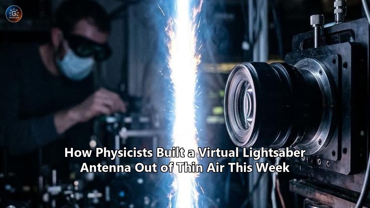
A research team led by North Carolina State University has achieved what long seemed confined to science fiction: turning the ambient atmosphere into a functional, reconfigurable radio antenna using an intense pulsed laser beam. In a peer-reviewed paper published in the IEEE Journal of Microwaves, the engineers demonstrated that a self-channeling column of ionized gas—a laser-induced plasma filament—can transmit radio signals through open air.
The resulting structure visually mirrors a glowing energy blade suspended in midair. Operating without physical wires, poles, or metallic rods, this plasma lightsaber antenna radiated a 30-megahertz Very High Frequency (VHF) signal, producing a 2.5-fold increase in received signal strength—a 150 percent gain over baseline ambient emissions.
The demonstration resolves a decades-old paradox in telecommunications and applied physics: how to alter the fundamental physical dimensions of an antenna instantaneously without relying on heavy motors, mechanical telescoping poles, or fixed metallic arrays. Because the antenna is forged entirely of light and ionized atmospheric gas, adjusting the laser parameters immediately changes its length, orientation, and resonant frequency. The moment the laser is shut off, the antenna vanishes back into thin air at the speed of light, leaving behind no physical structure, no radar footprint, and no metal wreckage.
                 CONTACTLESS CAPACITIVE FEED SYSTEM

          Laser Source
               │
               ▼  [Pulsed Laser Beam]
          ┌─────────┐
          │         │
     RF ──┤  ( O )  │◄── Capacitive Metal Ring (Contactless)
   Signal │         │    (Laser passes unobstructed through aperture)
          └────┬────┘
               │
               ▼  [Laser Ionization Path]
          ░░░░░░░░░░░
          █ █ █ █ █ █ ◄── Laser-Induced Plasma Filament
          █ █ █ █ █ █     ("Plasma Lightsaber Antenna")
          ░░░░░░░░░░░
               │
               ▼
     (((( Radiated VHF Waves ))))  --> 30 MHz Signal Transmission
                                       (150% Gain / 2.5x Signal Boost)
The experiment was spearheaded by Prya Darshni, a doctoral researcher at NC State, working alongside Paul Franzon, the Cirrus Logic Distinguished Professor of Electrical and Computer Engineering at the university, with optical and plasma measurements contributed by Arthur Dogariu of Texas A&M University and Princeton University.
"The plasma beam antenna looks like a lightsaber and is tunable, meaning we should be able to transmit across a broad range of frequencies," Darshni stated following the release of the findings. "And while we have not demonstrated its ability to serve as an antenna that can receive radio signals, there's no reason to believe it wouldn't also work as a receiver".
Franzon highlighted the immediate engineering advantages for aerospace systems. "This is an exciting new concept that enables one to be able to have a customized antenna without complex mechanical deployment mechanisms," Franzon said. "In low Earth orbit, there is sufficient air to form a plasma".
The Physics of Turning Ambient Air into a Conductor
To transform normal, non-conductive air into an active electromagnetic radiator, the researchers relied on the physics of laser filamentation—a non-linear optical phenomenon that occurs when an ultra-short laser pulse propagates through a dielectric gas.
Under ordinary environmental conditions, the atmosphere behaves as an electrical insulator. The electrons in nitrogen ($N_2$) and oxygen ($O_2$) molecules are tightly bound within atomic orbitals, preventing electric current from flowing. To construct an antenna without metal, those electrons must be liberated into an unbound, highly mobile sea of charge carriers.
The team achieved this by concentrating high-peak-power laser pulses into a microscopic optical corridor. When light of extraordinary intensity enters the air, it alters the optical properties of the medium itself through the optical Kerr effect. The refractive index of air ceases to be constant; instead, it scales proportionally with the local intensity of the laser beam:
$$n = n_0 + n_2 I$$
Where $n_0$ represents the linear refractive index of air, $n_2$ is the non-linear refractive coefficient, and $I$ is the optical intensity.
Because the laser beam is most intense at its spatial center, the air in the middle of the beam develops a higher refractive index than the surrounding air. This gradient acts as a distributed converging lens, continually focusing the light inward—a behavior known as Kerr self-focusing. As the beam focuses into an increasingly narrow diameter, its local electric field spikes to trillions of volts per meter, matching and exceeding the Coulomb forces binding molecular electrons.
At this threshold, multiphoton ionization and electron avalanche take over. Nitrogen and oxygen atoms shed outer electrons, generating a dense cylinder of ionized plasma.
               THE DYNAMICS OF LASER FILAMENTATION

    Laser Pulse Propagation ────────►

    1. Kerr Self-Focusing:
       Beam intensity spikes ──► Center index rises ──► Air acts as positive lens

    2. Dielectric Breakdown:
       Peak field exceeds ~10^13 W/cm² ──► Multiphoton ionization of N₂ & O₂

    3. Plasma Defocusing:
       Free-electron gas forms ──► Negative index contribution ──► Defocuses beam

    ─────────────────────────────────────────────────────────────────────────
    DYNAMIC EQUILIBRIUM:
    Self-Focusing  ◄═══════════════════════════════════►  Plasma Defocusing
                    Stable, Self-Guiding Plasma Filament
                    Conductive Electron Core ("Virtual Wire")
Left unchecked, this plasma formation would rapidly disperse light, as free electrons introduce a negative refractive index contribution that defocuses the beam. However, within a narrow intensity corridor, a balance emerges: Kerr self-focusing pulls the light together, while plasma defocusing pushes it apart.
The two opposing forces achieve a dynamic equilibrium. The laser pulse traps itself inside a continuous, self-guided channel that maintains its microscopic diameter across distances far exceeding the normal limits of optical diffraction.
Within this glowing filament, the gas possesses a high density of unbound electrons. In classical electrodynamics, conductors are defined by their abundance of mobile charge carriers capable of oscillating in resonance with external electric fields. According to the Drude model of electrical conductivity, a cold atmospheric plasma behaves precisely like a transient metal wire.
The plasma frequency ($\omega_p$), which dictates how the electron gas reacts to electromagnetic waves, is governed by electron density:
$$\omega_p = \sqrt{\frac{n_e e^2}{\varepsilon_0 m_e}}$$
Where:
- $n_e$ is the free electron density within the filament
- $e$ is elementary charge
- $\varepsilon_0$ is the permittivity of free space
- $m_e$ is electron mass
Along the outer boundaries of the filament, these free electrons migrate and oscillate in response to radio-frequency excitations, mimicking the "skin effect" seen on the outer surfaces of copper or aluminum wiring. The NC State team had succeeded in writing a conductive wire directly into the atmosphere.
The Contactless Feed: Solving the Physical Interface Dilemma
Transforming a laser filament into a functioning transmitter required overcoming a fundamental mechanical obstacle: connecting the radio-frequency source to the plasma.
In a conventional transmission tower, a solid copper coaxial cable is physically soldered or clamped to a metal radiator. Early theoretical models suggested using metal probes or mechanical electrodes inserted directly into the path of the ionized air. Yet in practice, doing so instantly ruins the filament.
Placing a solid metal contact directly into the path of an ultrafast laser creates immediate laser ablation, eroding the electrode while generating acoustic shockwaves and thermal quenching that distort and collapse the delicate plasma channel. Furthermore, direct high-voltage contact causes uncontrolled electrical arcing, injecting extreme noise into the transmitter and stripping away signal coherence.
The NC State researchers solved this dilemma by designing a completely non-invasive, contactless capacitive antenna feed.
                CROSS-SECTION: CONTACTLESS CAPACITIVE FEED

                         ┌───────────────────────┐
                         │   RF Generator Feed   │
                         └──────────┬────────────┘
                                    │
                              ┌─────┴─────┐
                              │ Metal Ring│
                              │ Capacitor │
                        ┌─────┴───────────┴─────┐
                        │   ┌───────────────┐   │
   Laser Influx =======►│   │ Open Aperture │   │======► Laser-Induced Filament
                        │   └───────────────┘   │        (Radiating Antenna)
                        └─────┬───────────┬─────┘
                              │ Capacitive│
                              │ Coupling  │
                              │   Field   │
                              └─────┬─────┘
                                    ▼
                      Non-Contact Energy Transfer
Instead of touching the plasma, the team manufactured a polished metal ring configured to function as a high-frequency capacitor. The ring sits suspended at the origin of the transmission zone. The laser beam is fired cleanly through the hollow center of the ring, passing through unobstructed and ionizing the atmosphere immediately downstream.
To transmit data, an RF signal generator routes high-frequency electrical current directly to the outer ring. As alternating current flows through the ring, it creates an intense, oscillating electromagnetic displacement field inside the aperture.
Because the plasma filament is packed with responsive free electrons, this surrounding field couples capacitively across the small air gap. The field grabs the electrons along the edges of the plasma channel and drives them into synchronized, linear oscillations matching the frequency of the input signal.
The process operates without a single atom of metal touching the plasma:
- The RF signal generator pumps a 30 MHz oscillating voltage into the metal ring capacitor.
- The ring converts this voltage into a concentrated, localized electromagnetic field.
- The field capacitively transfers energy across the dielectric void into the adjacent ionized gas column.
- Driven by the field, the plasma electrons surge back and forth along the length of the filament, acting as a center-fed monopole antenna.
- The vibrating charges shed electromagnetic radiation outward into the surrounding environment, successfully transmitting the radio signal.
During laboratory validation runs in Raleigh, North Carolina, the team drove the system at 30 MHz, sitting squarely within the Very High Frequency (VHF) band used globally for air traffic control, emergency broadcasting, and tactical communications. Operating through the contactless feed, the plasma column radiated clear, measurable signals, registering a 150 percent increase in signal strength over isolated baseline radiation.
Dynamic Resonant Tuning: Retiring the Telescoping Mast
The most profound operational feature of the plasma lightsaber antenna lies in the physics of electromagnetic resonance.
Every radio antenna constructed over the past century is bound by Maxwell's equations to a strict geometrical rule: an antenna's physical length must match a specific fraction of the radio wave's spatial wavelength ($\lambda$). In a standard half-wave dipole, maximum transmission efficiency occurs when the length of the radiator satisfies:
$$L = \frac{c}{2f}$$
Where $c$ is the speed of light and $f$ is the carrier frequency.
If a military unit or a scientific probe needs to broadcast across different radio bands, engineers must build an antenna that physically adapts. At 30 MHz, a half-wave antenna requires a metallic span of 5 meters (roughly 16.4 feet); at 300 MHz, it requires only 0.5 meters.
Historically, satisfying wideband communication meant using complex motorized telescoping rods, heavy spring-loaded deployment canisters, or sprawling multi-element arrays where different metal struts correspond to individual frequencies. Each moving part adds mechanical weight, electrical complexity, and failure points.
        CONVENTIONAL VS. PLASMA ANTENNA RECONFIGURABILITY

  CONVENTIONAL METAL ANTENNA:
  [==================== Metal Mast (Fixed Length / Motorized) ====================]
  • Fixed resonance: Modifying frequency requires mechanical motors or multiple antennas
  • High radar reflectivity (RCS) at all times
  • Vulnerable to physical bending, ice loading, and structural fatigue

  PLASMA LIGHTSABER ANTENNA:
  Laser Lens ──► ░░░░ [Tunable Plasma Length: L = f(Laser Energy, Pulse Focus)] ░░░░
  • Instant dynamic tuning: Change pulse energy/focus to alter resonant length instantly
  • Zero permanent radar signature: Turns off at the speed of light
  • Self-healing: Reformable every laser pulse; immune to physical impacts
The laser-generated system detaches frequency tuning from physical metal components. The length of a laser filament is controlled by optical parameters: pulse duration, pulse energy, beam diameter, and focal geometry.
If an operator wants to drop the transmission frequency from a high band to a lower band, they do not need to mechanically extend a mast. Instead, the laser system modifies its pulse profile, lengthening the plasma filament through the air. To jump to a higher frequency, the system narrows its focus or cuts pulse duration, instantly contracting the conductive channel.
This unlocks agility across the RF spectrum. The operator can sweep through high-frequency, very-high-frequency, and ultra-high-frequency bands using the same optical emitter, shifting frequencies in fractions of a second.
Beyond length, the plasma column's spatial direction can be adjusted instantaneously. By routing the laser beam through compact, high-speed galvanometer mirrors—the same optical steering mirrors used in laser eye surgery and industrial manufacturing—engineers can point the plasma filament in three dimensions at kilohertz speeds.
Rather than turning a multi-ton directional metal antenna dish using slow electric motors, the system steers the radiant plasma column through the air, repointing its radiation lobes and tracking receivers across the sky without a single external mechanical joint moving in the wind.
Radar Cross-Section and the Vanishing Transmitter
The operational implications of this technology extend far beyond convenient tuning. In defense, surveillance, and tactical electronic warfare, standard metal antennas are among the most dangerous liabilities on the battlefield.
A physical metal antenna is an unavoidable radar reflector. Long metallic poles, dishes, and wire whips possess high Radar Cross-Sections (RCS). Even when a ship, aircraft, or field vehicle is coated with state-of-the-art radar-absorbent paint, its antennas remain exposed, acting as metallic retroreflectors that show up distinctly on adversary surveillance systems.
Furthermore, modern signals intelligence (SIGINT) systems locate hostile units using automated direction-finding (DF), calculating the precise coordinates of a metallic mast the instant it radiates. Once located, a conventional radio mast cannot hide. It is vulnerable to anti-radiation missiles, artillery shrapnel, and physical jamming.
       TACTICAL CYCLE: LOW PROBABILITY OF INTERCEPT (LPI)

   STEP 1: Quiescent State           STEP 2: Transmission Pulse
   No laser emitted. Air is inert.   Laser fires; plasma ignites.
   RCS = 0. Metal Mast = None.       RF signal radiates instantly.

   Air: [  Invisible / Clear  ]      Air: [ ===== FILAMENT ===== ]

                     │                             │
                     ▼                             ▼
             STEP 4: Extinction            STEP 3: Emission Complete
             Laser pulse terminates.       Data burst fully broadcast.
             Plasma recombines (ns).       Target received signal.
             Structure disappears.         RF feed shuts down.

             Air: [  Invisible / Clear  ]
The plasma lightsaber antenna fundamentally alters these electronic warfare dynamics:
- Zero Quiescent Signature: In its inactive state, the antenna does not physically exist. There is no mast to reflect incoming radar pulses, no structure to cast a shadow, and nothing for visual reconnaissance to identify. The transmission array is safely housed behind optical apertures flush with the vehicle or outpost hull.
- Low Probability of Intercept (LPI) Transmissions: During burst communications, the system generates a laser filament for microsecond windows, transmits data, and shuts off. The plasma dissipates via electron-ion recombination in nanoseconds, leaving behind only neutral ambient air. By the time an adversary's direction-finding sensors register the radio wave, the physical antenna that emitted it has literally ceased to exist.
- Immunity to Kinetic and Shockwave Damage: If a conventional radio antenna is hit by bullet fragments, artillery blast shockwaves, or flying debris, the metal snaps, bending out of electrical resonance and rendering the radio system inoperable. A laser-generated plasma antenna cannot be bent, shattered, or broken. If a strong wind, an explosion shockwave, or flying shrapnel shears through the plasma channel, the filament automatically reconstitutes itself on the very next laser pulse—at rates of up to thousands of times per second.
- Electromagnetic Pulse (EMP) Survivability: High-altitude nuclear detonations or directed EMP weapons destroy conventional communications equipment by coupling massive voltage surges into external metal antennas, routing thousands of amps directly into sensitive receiver circuits. Because a laser plasma filament exists only when fired and relies on a contactless capacitive air gap, there is no permanent metallic transmission line to direct devastating external EMP currents into delicate internal transceivers.
The Aerospace and Satellite Frontier: Eliminating Mechanical Booms
Beyond terrestrial defense, the team from NC State, Texas A&M, and Princeton developed the technology with space operations directly in mind.
In astronautics, mechanical deployments represent one of the most persistent causes of catastrophic mission failure. Once a spacecraft separates from its launch vehicle, it must deploy its solar panels, science instruments, and communications antennas. For decades, long-wavelength radar and deep-space communications have required long, extendable metallic booms.
               HISTORICAL MECHANICAL DEPLOYMENT HAZARDS

   1991: Galileo Jupiter Probe        MODERN ERA: SmallSats & CubeSats
   ┌─────────────────────────────┐    ┌─────────────────────────────┐
   │ High-Gain Antenna (HGA)     │    │ Highly constrained volumes  │
   │ umbrella ribs fail to pop   │    │ make spring-loaded hinges   │
   │ open in deep space due to   │    │ prone to binding, thermal   │
   │ cold-welded guide pins.     │    │ warping, and motor lockups. │
   └──────────────┬──────────────┘    └──────────────┬──────────────┘
                  │                                  │
                  ▼                                  ▼
   Result: Data transfer throttled    Result: Complete spacecraft loss
   from 134 kbps down to 10 bps.      or critical sensor blinding.
The space exploration graveyard is filled with probes crippled by stuck mechanical antennas. The most famous example remains NASA's $1.6-billion Galileo mission to Jupiter, launched in 1989. When engineers attempted to deploy its 4.8-meter high-gain umbrella antenna in 1991, thermal expansion and structural friction bound its titanium ribs. Despite years of troubleshooting, the antenna never opened, forcing NASA to transmit precious scientific discoveries back to Earth across millions of miles using a low-gain antenna at a trickle of 10 bits per second.
Similar risks plague modern CubeSats and SmallSats. These miniaturized spacecraft have tiny chassis volumes—often measuring just 10 by 10 by 30 centimeters—yet are tasked with carrying out advanced radar mapping, ionospheric sounding, and interplanetary exploration. Squeezing a long, high-frequency antenna into a shoe-box-sized satellite requires complex origami folds, spring-loaded hinges, and burn-wire release systems, all of which are vulnerable to thermal warping, cold-welding in a vacuum, and mechanical binding.
The laser plasma system bypasses this vulnerability by trading mechanical hardware for non-linear optics.
"Satellites and space exploration technologies are one potential area of interest, because payload and the ability to scan across a wide range of frequencies are both important considerations," Darshni explained during the system's unveiling.
Franzon pointed to the upper reaches of Earth's atmosphere as an immediate deployment venue: "In low Earth orbit, there is sufficient air to form a plasma".
Between altitudes of 150 and 500 kilometers—the orbit where Earth observation platforms, commercial imaging constellations, and the International Space Station operate—the environment is not a pure vacuum. It is the thermosphere, filled with diffuse, neutral atomic oxygen and nitrogen.
A satellite equipped with a compact optical laser system could point its beam directly outside the spacecraft hull into the ambient thermospheric gas, ionizing a thin, rigid plasma filament stretching tens of meters into space alongside the craft. The satellite would possess a long, multi-band, steerable antenna for high-power VHF or UHF planetary radar sounding without carrying a single pound of physical booms or motorized deployment gimbals.
For operations deeper into the complete vacuum of space, researchers envision pairing the optical system with micro-nozzles that inject tiny, low-mass puffs of neutral gas—such as argon or xenon, identical to the propellants used in satellite ion thrusters—along the optical track. The laser instantly converts the gas puff into a conductive plasma filament, transmitting data before the gas disperses into the vacuum.
The Lineage of Plasma Antennas: From Fluorescent Tubes to Free Air
While using ionized gas to interact with radio waves is rooted in century-old physics, the NC State breakthrough represents a departure from all prior experimental plasma antennas.
The conceptual roots trace back to 1919, when inventor J. Hettinger filed early patent concepts exploring whether ionized gas paths could guide radio currents. In the modern era, military agencies, including the U.S. Office of Naval Research and the Defense Advanced Research Projects Agency (DARPA), funded extensive studies throughout the late 1990s and 2000s into Gaseous Plasma Antennas (GPAs).
                     THE EVOLUTION OF PLASMA ANTENNAS

   GENERATION 1: Enclosed Gaseous Tubes (1990s - 2010s)
   ┌────────────────────────────────────────────────────────┐
   │ [Glass / Quartz Tube Filled with Neon/Argon/Mercury]   │
   └────────────────────────────────────────────────────────┘
   • Mechanically fragile: Retains all physical vulnerabilities of metal
   • Fixed dimensions: Cannot change length or shape dynamically
   • Bulky power envelopes: Requires high continuous discharge currents

                                │
                                ▼
   GENERATION 2: The Free-Air Laser Filament (NC State, 2026)
   · · · · ░░░░░░░░░░░░ [Unconfined Open Atmosphere] ░░░░░░░░░░░░ · · · ·
   • Pure light and ambient air: No quartz tubes, glass vessels, or enclosures
   • Dynamically scalable: Length changes instantly via laser focus/energy
   • Truly invisible: Disappears completely the instant the laser is turned off
Those early systems shared a crippling limitation: the ionized gas had to be physically sealed inside dielectric containment vessels, typically quartz or borosilicate glass tubes filled with low-pressure neon, argon, or mercury vapor.
These tube-bound antennas proved the core electromagnetic principles. When the gas was excited by an electric current or microwave horn, it ionized and functioned as an effective RF radiator. When the current was removed, the gas de-ionized, rendering the tube transparent to incoming enemy radar.
Yet from an operational standpoint, Generation 1 GPAs solved almost none of the practical mechanical challenges:
- Fragile Enclosures: Replacing a metal pole with a hollow glass tube made the antenna far more fragile. A quartz tube shatters under the vibration of a launch vehicle, the recoil of a naval deck gun, or the impact of environmental debris.
- Fixed Geometric Footprint: Because the tube was a rigid, physical object, the antenna could not change its length. Sweeping frequencies still meant installing separate, fixed-length tubes for every desired band.
- Bulky Deployments: Spacecraft still required mechanical hinges and release mechanisms to push the glass tubes out of satellite chassis, leaving the primary points of failure unaddressed.
The work by Darshni, Franzon, and Dogariu represents Generation 2 plasma antenna design. By pairing ultrafast laser filamentation with contactless capacitive excitation, the team freed the plasma antenna from physical containment.
The atmosphere itself serves as both the raw material and the container. There is no glass to fracture, no internal gas to leak, and no structural framework restricting the physical dimensions of the antenna.
Thermodynamic and Environmental Obstacles
Despite the success of the 30 MHz laboratory test, transitioning a plasma lightsaber antenna from a controlled optical laboratory bench into reliable, operational field equipment involves significant physics and engineering hurdles.
The most glaring real-world challenge is Size, Weight, and Power (SWaP) efficiency. Generating and sustaining a laser-induced plasma filament in open atmosphere requires high peak power. While the radio signal itself was broadcast at modest transmission energies, the optical engine driving the ionization relies on an ultrafast laser system delivering femtosecond or picosecond pulses.
In a pristine laboratory connected to a municipal power grid, operating water-cooled laser chassis is trivial. In a field combat outpost, a tactical drone, or a CubeSat with an average power budget of 20 watts, delivering the electrical draw demanded by ultrafast lasers presents an immediate barrier.
Until diode-pumped solid-state (DPSS) and fiber lasers achieve higher wall-plug electrical efficiency and smaller footprints, deploying continuous plasma filaments will be limited to heavy, power-rich platforms—such as naval destroyers, fixed forward operating bases, and heavy aerospace craft.
                  CRITICAL ENGINEERING TRADEOFFS

       STRENGTHS & ADVANTAGES          LIMITATIONS & VULNERABILITIES
  ┌──────────────────────────────┐┌──────────────────────────────────┐
  │ • Instant multi-band tuning  ││ • Significant laser power demand│
  │ • Zero physical radar cross  ││ • Atmospheric phase turbulence  │
  │ • Impervious to metal fatigue││ • High thermal noise floor (Rx) │
  │ • Steerable without motors   ││ • Audible crackling & acoustics │
  │ • No satellite boom failures ││ • Trace ozone (O₃) generation   │
  └──────────────────────────────┘└──────────────────────────────────┘
A second critical limitation centers on atmospheric conditions. Laboratory air is climate-controlled, dry, and clean. In open-air tactical and aerospace environments, the laser beam must pass through rain, sea-spray, dense fog, swirling sandstorms, and severe thermal turbulence.
Suspended water droplets and airborne particulates scatter laser light through Mie and Rayleigh scattering, draining optical power and driving the beam's intensity below the multiphoton ionization threshold. Strong atmospheric crosswinds and thermal thermals also warp the laser’s focal point, potentially bowing or interrupting the continuous line of the filament.
Then there is the unproven question of reception.
In classical antenna theory, the principle of reciprocity dictates that any structure capable of transmitting an electromagnetic signal must also be capable of receiving it. In an ideal mathematical space, an incident radio wave sweeps over the free electrons in the plasma filament, causing them to oscillate and generate an electromagnetic field that the capacitive ring picks up and routes to a receiver.
In practice, an atmospheric plasma is a chaotic thermodynamic soup. High-density free electrons continually collide with neutral nitrogen and oxygen molecules at rates exceeding $10^{12}$ collisions per second. This Brownian motion generates considerable thermal Johnson–Nyquist noise.
If the plasma filament's internal electrical noise floor drowns out incoming signals, detecting microvolt-level signals from distant transmitters will prove exceptionally difficult. The NC State team openly acknowledged this hurdle, verifying that while transmission is clearly proven, reliable signal reception remains an unverified hypothesis in need of physical laboratory confirmation.
Finally, the physical presence of the filament introduces local environmental signatures:
- Acoustic Shockwaves: Atmospheric ionization is violently rapid. As the laser pulse superheats the optical corridor, the air expands supersonically, producing an audible, rapid crackling sound resembling high-voltage discharge or static arcs. While the antenna lacks a radar signature, its localized acoustic profile would be unmistakable to nearby human ears or directional acoustic microphones.
- Chemical Reactions: Stripping electrons from ambient nitrogen and oxygen triggers plasma chemistry. The dissociated atoms recombine into trace concentrations of ozone ($O_3$) and various nitrogen oxides ($NO_x$), requiring proper ventilation if operated in semi-confined settings.
The Next Milestones: Phased Arrays, Reception, and Field Trials
With the initial proof-of-concept published, researchers in advanced communications, aerospace, and defense are tracking the next phases of development. The transition from laboratory feasibility to field deployment will center on four technical milestones over the coming months and years:
                  RESEARCH AND MILESTONE ROADMAP

  PHASE 1 (Completed):
  Laboratory proof-of-concept; contactless capacitive feed;
  30 MHz VHF transmission validated with 150% gain.

  PHASE 2 (Upcoming 12-24 Months):
  Signal reception testing (validating electromagnetic reciprocity);
  Noise-floor suppression and thermal drift characterization.

  PHASE 3 (24-36 Months):
  Multi-filament arrays; phase-shifting via split optical beams;
  Dynamic laser-plasma phased arrays without analog phase shifters.

  PHASE 4 (Long-Term Horizon):
  Sub-orbital sounding rocket & low-pressure chamber testing;
  Thermospheric satellite integration trials in low Earth orbit.
The immediate next objective is verifying RF reception. Darshni, Franzon, and their collaborators are already designing secondary receiver tests, focusing on filtering out plasma collision noise to capture external broadcast signals through the contactless capacitive coupler. Proving two-way transceiving capability will determine whether the technology can serve as a full communications terminal or will remain restricted to specialized transmission missions.
The second major milestone involves multi-filament plasma phased arrays. By splitting a single high-power laser beam into dozens of parallel filaments through diffractive optical elements, engineers could generate an entire array of virtual antennas in the sky simultaneously.
By slightly altering the relative optical path length of each beam, researchers can change the phase of individual plasma elements. This would allow automated beamforming—focusing radio emissions into razor-thin, steerable directional beams—without the bulky analog phase-shifters and complex networks required by solid-state phased-array radar dishes today.
The third milestone will take the hardware out of the laboratory and into environmental test chambers, including atmospheric wind tunnels, humidity-controlled tanks, and low-pressure vacuum chambers that simulate the thin upper atmosphere of low Earth orbit. These trials will establish exact baseline figures for how much laser energy is required to maintain a functional filament under diverse weather conditions and ambient pressures.
The demonstration at North Carolina State University marks an inflection point in how humans interface with the electromagnetic spectrum. For more than a century, expanding telecommunications has meant mining, refining, bending, and mounting physical metal. By showing that a precisely tailored pulse of light can transform the air itself into a functional radiator, physicists have taken communications hardware off the physical circuit board and placed it into the open atmosphere.
Reference:
- https://www.facebook.com/NCStateECE/posts/-lightsaber-style-antennas-are-here-ece-phd-student-prya-darshni-and-cirrus-logi/1698165565649482/
- https://news.ncsu.edu/2026/10/plasma-beam-antenna/
- https://www.gadgetreview.com/scientists-just-built-a-lightsaber-like-antenna-that-uses-laser-ionized-air
- https://modernmechanics24.com/post/lasers-turn-air-into-a-radio-antenna/
- https://www.youtube.com/shorts/nnq8G2djoVw
- https://www.studenti.it/antenna-a-fascio-di-plasma-come-un-laser-puo-rendere-sintonizzabili-le-onde-radio-e-perche-serve-nello-spazio.html
- https://news.ncsu.edu/2026/10/plasma-beam-antenna/
- https://lifeboat.com/blog/2026/10/lightsaber-like-plasma-antenna-uses-laser-ionized-air-to-transmit-radio-waves
- https://www.facebook.com/physorg/posts/a-lightsaber-like-beam-of-laser-ionized-air-has-transmitted-radio-wavesthe-first/1588413019980747/
- https://news.ycombinator.com/item?id=49977396
- https://www.pprune.org/military-aviation/674325-plasma-beam-antenna.html
- https://tucumanhoyendia.com.ar/amp/117928/la-primera-antena-laser-que-transmite-ondas-de-radio
- https://www.labcompare.com/617-News/628619-Researchers-Demonstrate-First-ever-Plasma-Beam-Antenna/
- https://www.facebook.com/actuallyscience/posts/researchers-have-demonstrated-a-technique-that-uses-a-laser-to-produce-a-plasma-/1427126112966855/
- https://ece.ncsu.edu/