
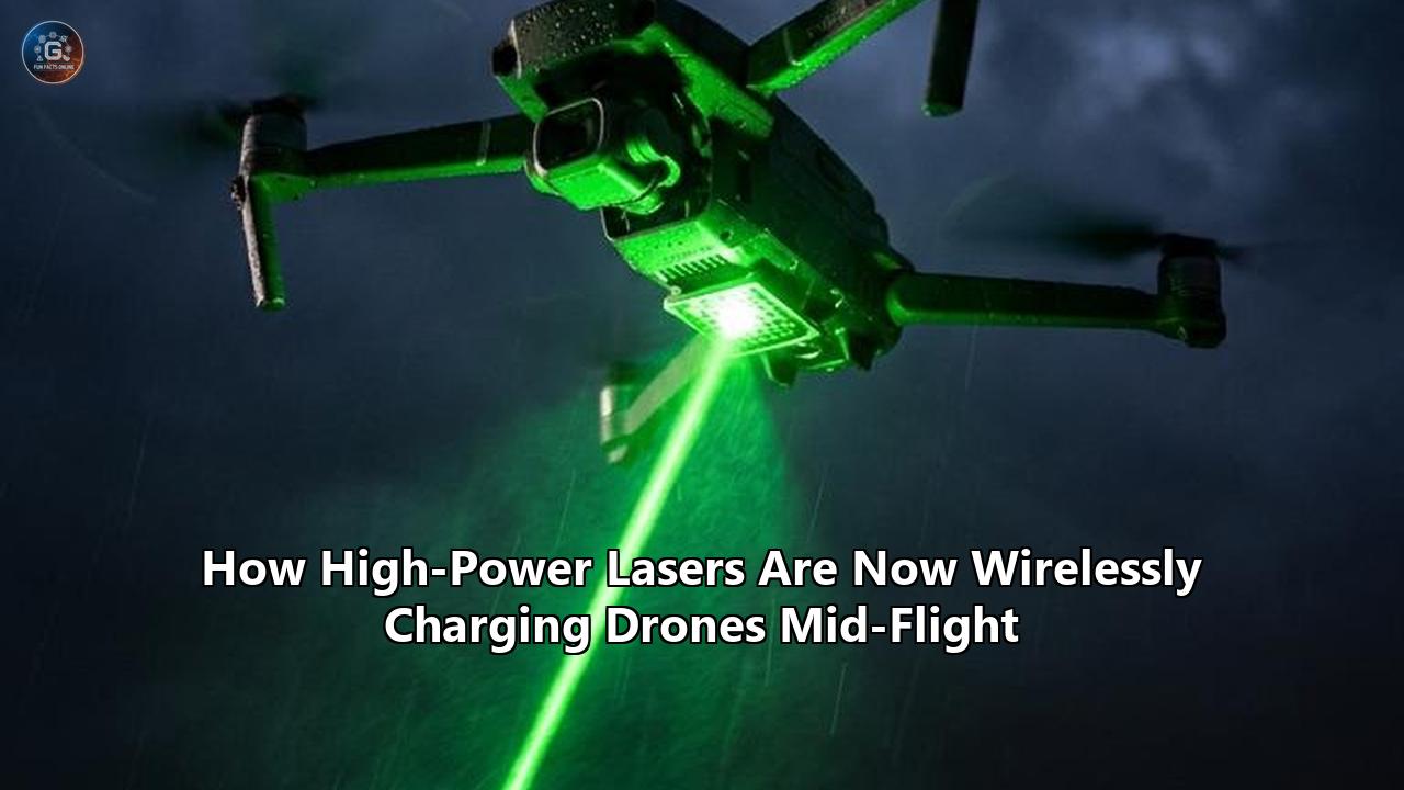
A series of field trials and laboratory breakthroughs have validated a long-sought concept in autonomous aviation: using high-powered ground lasers to wirelessly recharge unmanned aerial vehicles (UAVs) while they are flying.
The most recent milestone came when researchers from the Civil Aviation University of China and Tsinghua University published results in the journal Matter & Light, demonstrating a tandem optical receiver capable of turning incoming laser energy into electrical power at a record 38.49% conversion efficiency while actively managing severe thermal stress. The prototype successfully harvested high-intensity monochromatic laser light to drive a drone’s propulsion system, solving key overheating hurdles that have historically degraded airborne receivers.
This laboratory result follows a landmark field demonstration by the U.S. Defense Advanced Research Projects Agency (DARPA). Under its Persistent Optical Wireless Energy Relay (POWER) program, DARPA delivered more than 800 watts of optical power over a distance of 8.6 kilometers (5.3 miles) at the White Sands Missile Range in New Mexico. Executed via the POWER Receiver Array Demo (PRAD) with technical evaluation from the U.S. Naval Research Laboratory (NRL) and receiver design by Teravec Technologies, the test transferred over one megajoule of total energy through atmospheric haze. Concurrently, defense firm PowerLight Technologies completed subsystem validation for its PTROL-UAS (Power Transfer for Resilient Operational Logistics) system, preparing six-pound airborne receivers for continuous flight-charging trials.
Together, these achievements demonstrate that optical power beaming has progressed from a theoretical physics concept into an operational engineering reality. By converting ground-supplied laser photons into high-voltage direct current in real time, engineers are opening up a paradigm where aircraft flight times are bounded not by onboard fuel reserves or battery energy density, but by mechanical wear and component lifespan.
Understanding how this technology functions requires examining the underlying wave physics, advanced material science, closed-loop tracking algorithms, and economic factors driving mid-air energy transmission.
The Physics of Optical Energy Beaming: Light as a Power Cord
To appreciate why lasers are selected for long-range airborne energy transfer, one must contrast optical power transmission with magnetic and radiofrequency (RF) alternatives.
Inductive coupling and magnetic resonance—the principles behind smartphone charging pads—rely on near-field magnetic fields. Their energy density drops off according to the inverse-cube law ($\frac{1}{r^3}$) relative to distance ($r$), limiting practical power transfer to fractions of a meter. Microwave power transmission operates in the far field and can cover kilometers, but the physical laws of diffraction demand immense aperture sizes. For a microwave system emitting at 2.45 GHz or 5.8 GHz, delivering focused power over several kilometers requires transmitting dishes tens of meters wide and airborne rectifying antennas (rectennas) of similar scale to capture the dispersed beam spot.
Laser-based optical power transfer bypasses these size constraints by operating at vastly shorter wavelengths, typically in the near-infrared (NIR) spectrum between 800 nanometers and 1070 nanometers, or near the eye-safe band around 1550 nanometers.
$$\lambda_{\text{laser}} \approx 800 \text{ nm} - 1550 \text{ nm} \quad \ll \quad \lambda_{\text{microwave}} \approx 5 \text{ cm} - 12 \text{ cm}$$
Because beam divergence is directly proportional to wavelength ($\theta \approx \frac{\lambda}{D}$, where $\theta$ is the divergence angle, $\lambda$ is wavelength, and $D$ is aperture diameter), an NIR laser beam can be focused into a tight spot just tens of centimeters in diameter across distances of several miles. This tight spatial coherence enables high power density (irradiance, measured in watts per square centimeter) to hit a small, lightweight receiver target mounted on a moving drone.
                     CONVENTIONAL VS. OPTICAL WIRELESS POWER

  [Inductive Coupling]   Near-field magnetic fields
                         Distance: < 5 centimeters
                         Aperture: Small | Dropoff: 1/r³

  [Microwave Beaming]    Far-field radio waves (2.45 GHz - 5.8 GHz)
                         Distance: Kilometers
                         Aperture: Tens of meters (large antennas required)

  [Laser Power Beaming]  Far-field coherent light (800 nm - 1550 nm)
                         Distance: 8+ Kilometers
                         Aperture: Decimeters (compact 6 lb airborne receiver)
Photonic Tuning and Bandgap Matching
Standard solar panels perform inefficiently when irradiated by high-power lasers because they are designed for broad-spectrum sunlight (AM1.5 solar spectrum, spanning 300 nm to 2500 nm). When broadband silicon photovoltaic cells absorb photons with energy much higher than their bandgap ($E_g = 1.11 \text{ eV}$), the excess photon energy is lost instantly through thermal relaxation (phonon emission), heating the cell rather than generating current. Photons with energy lower than the bandgap pass straight through without being absorbed.
Optical power beaming circumvents these spectral loss mechanisms by pairing a monochromatic light source—a fiber or diode laser emitting at a single wavelength—with specialized laser-tuned photovoltaics (LTPVs).
When the laser's photon energy ($h\nu$) is matched precisely to the semiconductor receiver's electronic bandgap ($E_g$), thermalization losses drop toward zero:
$$h\nu \approx E_g + \epsilon \quad (\text{where } \epsilon \rightarrow 0)$$
Under ideal laboratory conditions, monochromatic single-junction cells made from Gallium Arsenide (GaAs) or Indium Gallium Phosphide (InGaP) can achieve theoretical photovoltaic conversion efficiencies exceeding 50% to 60%, far higher than the ~33% Shockley-Queisser limit for single-junction silicon under broad sunlight.
However, translating these high theoretical efficiencies into operational hardware mounted on an airborne drone introduces a new challenge: extreme heat accumulation.
Overcoming the Thermal Wall: The 38.49% Efficiency Breakthrough
When a high-power laser beam delivers hundreds or thousands of watts per square meter to a small receiver plate mounted on an aircraft, even high conversion efficiency leaves a substantial fraction of energy absorbed as thermal heat.
If a 1,000-watt laser strikes a 30% efficient optical receiver, 300 watts become usable electricity while 700 watts instantly transform into localized heat. In uncooled environments, receiver temperatures quickly spike past 80°C to 90°C (176°F to 194°F). This rapid heating causes severe efficiency degradation, known as the negative temperature coefficient of photovoltaics, and risks delaminating semiconductor substrates or melting lightweight structural composites.
                     LASER POWER & THERMAL DISSIPATION BUDGET

     Incoming Laser Energy: 1,000 W
     ├── Converted to Electrical Power (38.49%): ~385 W ──> Propellers / Avionics
     └── Lost as Localized Thermal Heat (61.51%): ~615 W
          ├── Harvested by Thermoelectric Layer (TEG)
          ├── Shielded by Sb₂Se₃ Nanocrystal Thermal Barrier
          └── Dissipated via Drone Wing Aerodynamic Air Channels
The July 2026 breakthrough led by senior author Jianhua Han at the Civil Aviation University of China, in collaboration with Tsinghua University, directly targeted this thermal obstacle. The research team engineered a hybrid, dual-action receiver dubbed the Perovskite Laser Cell-Thermoelectric tandem device (PLC-TE).
                PLC-TE TANDEM RECEIVER ARCHITECTURE

  Laser Beam  ━━━━━>  [ Top Layer: Perovskite Photovoltaic ]
                      ├── Monochromatic Photon-to-Electricity Conversion
                      └── High Operating Temperature Output
                                    │
                      [ Middle Layer: Sb₂Se₃ Nanocrystals ]
                      └── Thermal Barrier (Maintains ΔT Gradient)
                                    │
  Airflow     ━━━━━>  [ Bottom Layer: Thermoelectric Generator (TEG) ]
                      └── Heat-Difference-to-Electricity Harvesting
The Perovskite-Thermoelectric Architecture
Instead of fighting temperature differentials, the Chinese research team designed a multi-layer device that actively harvests excess thermal energy while protecting the underlying airframe:
- The Primary Photovoltaic Layer: The top layer utilizes a halide perovskite semiconductor. Perovskites possess tunable optical bandgaps, high absorption coefficients, and superior charge-carrier mobility. The crystal lattice was spectrally tuned specifically to absorb high-flux monochromatic green laser light, achieving direct photon-to-electron conversion.
- The Thermoelectric Harvesting Layer: Below the perovskite cell sits a thermoelectric generator (TEG). Thermoelectric devices operate via the Seebeck effect: when a steep temperature gradient ($\Delta T$) exists across a thermoelectric material, charge carriers (electrons or holes) diffuse from the hot side to the cold side, generating an auxiliary electric voltage. By capturing heat flowing from the hot perovskite top layer to the cooler rear surface, the TEG converts waste heat into secondary electrical power.
- Nanocrystal Thermal Barrier Insulation: High thermal conductivity between layers can collapse the temperature gradient, stopping thermoelectric generation and overheating the aircraft wing. To prevent this, the researchers embedded synthesized antimony triselenide ($Sb_2Se_3$) nanocrystals between the device structures. Antimony triselenide acts as a selective thermal insulator due to its low lattice thermal conductivity, maintaining the high internal $\Delta T$ required for the thermoelectric layer to function while stopping thermal energy from bleeding into the drone's structural airframe.
- Integrated Aerodynamic Cooling: To manage the cold side of the thermoelectric module, the team integrated the receiver array into the underside of the drone wing, incorporating custom air channels. As the aircraft flies or spins its propellers, high-velocity slipstream air flows through these wing channels, continuously stripping heat away from the rear heatsink.
During static laboratory testing, this integrated PLC-TE device achieved an energy conversion efficiency of 38.49% under direct high-power laser illumination. This surpasses the peak efficiency benchmarks reported for conventional perovskite-silicon tandem solar cells, marking a significant advancement in turning high-flux directed light into flight power.
Precision Alignment: Tracking a Moving Target Through Atmosphere
Generating and converting laser light is only half the battle. Delivering a focused beam of light across miles of open air onto a small receiver mounted beneath a bouncing, weaving drone requires advanced optical engineering and control systems.
                     CLOSED-LOOP BEAM TRACKING & CONTROL

 +------------------------+                      +-----------------------+
 | Ground Transmitter     |                      | In-Flight UAV Receiver |
 |                        |                      |                       |
 |  [Fiber Laser Array]   | ━━━━ Monochromatic ━>| [Retroreflector Ring] |
 |                        |       Laser Beam     |           │           |
 |  [Fast Steering Mirror]|<━━ Optical Telemetry ━━━ Backscatter Signal  |
 |  [Adaptive Optics Engine]                     |           │           |
 +------------------------+                      | [LTPV Receiver Array] |
             │                                   +-----------------------+
             ▼                                               │
   Detects Atmospheric                                       ▼
 Turbulence & Adjusts Phase                        Powers Propulsion Motor
The Atmospheric Obstacle Course
When a high-power laser beam travels through the atmosphere, it encounters three main physical disruptions:
- Rayleigh Scattering: Molecular scattering caused by nitrogen and oxygen particles, dominant at shorter optical wavelengths ($\propto \frac{1}{\lambda^4}$).
- Mie Scattering: Particle scattering caused by dust, water droplets, aerosols, and smoke particles whose physical size is comparable to the laser wavelength.
- Atmospheric Turbulence ($C_n^2$): Micro-fluctuations in the atmosphere's refractive index driven by ground heat, air currents, and temperature gradients. Turbulence acts as a chaotic series of weak lenses, causing the beam to wander (beam wander), broaden beyond its ideal focus (beam breakup), and fluctuate in intensity (scintillation).
To overcome these distortions, state-of-the-art transmitters—such as those developed by PowerLight Technologies and deployed in DARPA’s POWER program—use adaptive optics (AO) systems originally engineered for astronomical telescopes and missile defense systems.
                 ATMOSPHERIC DISTORTION & ADAPTIVE CORRECTION

   Uncorrected Beam:
   Laser Source ━━━> [Atmospheric Turbulence] ━━━> Scattered/Broadened Beam (Power Loss)

   Adaptive Optics Corrected Beam:
   Laser Source ━━━> [Deformable Mirror] ━━━> Pre-Distorted Wavefront
                                                   │
                                         [Atmospheric Turbulence]
                                                   │
                                                   ▼
                                         Clean Focused Beam Spot
An adaptive optics system samples the atmospheric path hundreds or thousands of times per second using a low-power guide star laser or optical backscatter from retroreflectors mounted on the target drone. A Shack-Hartmann wavefront sensor measures phase aberrations introduced by the air.
Computers calculate the exact inverse distortion and apply it in real time to a deformable mirror—a specialized mirror backed by hundreds of microscopic piezoelectric actuators. By warping the shape of the mirror surface in real time, the system pre-distorts the outgoing laser beam so that as it travels through atmospheric turbulence, the distortions cancel out, delivering a crisp, focused beam spot onto the drone's receiver array.
 +--------------------------------------------------------------------------+
 |                      OPTICAL BEAM TRACKING SUBSYSTEMS                    |
 +--------------------------------------------------------------------------+
 | System Module          | Mechanism & Function                            |
 +------------------------+-------------------------------------------------+
 | Coarse Gimbal Tracking | Electro-optical/infrared (EO/IR) cameras lock   |
 |                        | onto the airframe to handle large slewing       |
 |                        | movements across the sky.                       |
 +------------------------+-------------------------------------------------+
 | Fine Steering Mirrors  | High-frequency piezoelectric mirrors make        |
 | (FSMs)                 | micro-radian adjustments to keep the beam       |
 |                        | centered within millimeter tolerances.          |
 +------------------------+-------------------------------------------------+
 | Retroreflector Ring    | Precision corner-cube prisms arrayed around the |
 |                        | airborne receiver reflect tracking signals back |
 |                        | to ground sensors.                              |
 +------------------------+-------------------------------------------------+
 | Safety Interlock       | Radar and optical guard rings automatically cut |
 | Systems                | beam power in milliseconds if an object crosses |
 |                        | the transmission path.                          |
 +------------------------+-------------------------------------------------+
Safety Interlocks and Airspace Protection
Shooting high-power lasers through open airspace presents clear hazards. An unattenuated Class 4 laser beam capable of delivering kilowatts of power can blind aircraft pilots, damage satellite sensors, or ignite fires if misaligned.
To operate within civil and military airspaces, systems like PowerLight’s PTROL-UAS incorporate multi-layered, fail-safe safety interlocks:
- Optical Safety Curtains: The narrow power beam is surrounded by a low-intensity, wide-angle sensing beam. If an uncooperative object—such as a bird, commercial aircraft, or cloud—enters the perimeter beam, optical sensors detect the reflection and cut off the primary power laser in milliseconds before the object reaches the high-intensity core.
- Bidirectional Telemetry Handshakes: The drone and ground station maintain a continuous encrypted RF or optical data link. The ground laser fires only while receiving active status pulses from the drone's position sensors. If the drone performs a sudden maneuver, suffers tracking drift, or loses alignment, the handshake breaks and the laser turns off before the beam strays off target.
- Geofenced Elevation Buffers: Transmitters feature physical and software lockouts that prevent firing below specific elevation angles above the horizon, keeping high-flux energy safely above ground personnel and vehicles.
Flight Dynamics and Payload Economics: The Power-to-Weight Shift
Eliminating the need to carry heavy chemical fuels or dense battery packs changes the fundamentals of aircraft design.
For conventional electric UAVs, flight endurance is limited by battery energy density. High-performance lithium-ion and lithium-sulfur batteries offer energy densities around 250 to 350 watt-hours per kilogram ($\text{Wh/kg}$). In contrast, aviation jet fuel yields roughly 12,000 $\text{Wh/kg}$.
Because electric batteries do not shed mass as they discharge energy, an electric drone must carry its heavy battery payload throughout its entire flight, creating a strict tradeoff between battery mass, payload capacity, and airborne endurance.
                         BATTERY MASS VS. LASER RECEIVER

  [Conventional Electric UAV]
  ┌─────────────────────────────────────────────────────────────┐
  │                      Heavy Battery Pack                     │
  │                      (50% - 70% Total Aircraft Mass)        │
  └─────────────────────────────────────────────────────────────┘
  Endurance: Limited to 45 - 90 Minutes

  [Laser-Powered Wireless Charging UAV]
  ┌───────────────┬─────────────────────────────────────────────┐
  │ Light Receiver│           Expanded Sensor / Cargo           │
  │ (6 lbs Array) │              Payload Capacity               │
  └───────────────┴─────────────────────────────────────────────┘
  Endurance: Indefinite Continuous Flight (Bounded by Mechanics)
In an optical wireless drone charging setup, the primary heavy energy storage component is moved out of the sky and onto the ground. The airborne platform exchanges a bulky multi-kilogram battery pack for a lightweight receiver array and a small buffer battery.
Weight Budget Breakdown: Standard vs. Laser-Charged Drone
To highlight this difference, consider a medium-range surveillance drone engineered for an 8-hour continuous mission footprint:
 +--------------------------------------------------------------------------+
 |              WEIGHT BUDGET COMPARISON: 25 KG MAXIMUM TAKE-OFF WEIGHT     |
 +--------------------------------------------------------------------------+
 | Component              | Standard Battery Aircraft| Laser Receiver Aircraft|
 +------------------------+--------------------------+----------------------+
 | Airframe & Avionics    | 7.5 kg                   | 7.5 kg               |
 | Propulsion Motors      | 3.0 kg                   | 3.0 kg               |
 | Primary Battery Pack   | 12.0 kg (Li-ion)         | 1.5 kg (Small Buffer)|
 | Laser Receiver Array   | N/A                      | 2.7 kg (6 lbs)       |
 | Usable Payload Capacity| 2.5 kg                   | 10.3 kg              |
 | Maximum Continuous Flight| ~2 hours               | Indefinite (Days)    |
 +------------------------+--------------------------+----------------------+
By shrinking energy storage down to a lightweight 1.5 kg buffer battery—used only to maintain flight during brief beam interruptions or transfers between ground stations—the aircraft frees up over 7.8 kg of capacity. This surplus weight can be repurposed for advanced sensor suites, radar arrays, telecommunication relays, or cargo, while extending operational endurance indefinitely.
                    THE EFFICIENCY LOSS CHAIN

  Ground Electrical Input: ~4,000 W (100%)
            │
            ▼ [Fiber Laser Diode - ~50% Efficiency]
  Optical Laser Output: ~2,000 W (50%)
            │
            ▼ [Atmospheric Transmission - ~80% Throughput]
  Arriving Light at UAV: ~1,600 W (40%)
            │
            ▼ [PLC-TE Receiver Array - ~38.49% Conversion]
  Usable Flight Power: ~615 W (15.4% Net System Efficiency)
The Energy Cost Factor
While laser charging offers impressive flight performance, it comes at the expense of total electrical efficiency.
Transforming electrical power into optical laser light, transmitting it through miles of atmosphere, and converting it back into electricity incurs losses at every stage:
- Electricity-to-Laser Conversion: Modern industrial fiber lasers operate at roughly 45% to 50% wall-plug efficiency.
- Atmospheric Transmission: Depending on distance, humidity, and haze, atmospheric absorption and scattering consume 10% to 30% of optical energy.
- Laser Photovoltaic Conversion: State-of-the-art tandem receivers convert 38.49% of incoming photon energy back into electrical current.
Multiplying these efficiencies reveals a net system efficiency of 15% to 20%:
$$\text{Net Efficiency} = \eta_{\text{laser}} \times \eta_{\text{atmosphere}} \times \eta_{\text{receiver}} \approx 0.50 \times 0.80 \times 0.3849 \approx 15.4\%$$
For ground-based electricity consumers, a 15% end-to-end efficiency rate would be financially impractical. But for airborne operations—where the primary cost driver is not raw grid electricity but mission downtime, landing logistics, pilot intervention, and short battery lifespans—paying a grid power premium to keep an aircraft airborne indefinitely is a compelling trade-off.
Defense vs. Commercial Deployments: Operational Roles
The initial push behind optical power beaming stems from military logistics needs, but commercial and industrial applications are expanding as the technology matures.
                     FIELD APPLICATION DOMAINS

  MILITARY & DEFENSE ARCHITECTURE        COMMERCIAL & CIVILIAN ARCHITECTURE

  ┌───────────────────────────────┐      ┌───────────────────────────────┐
  │ Forward Operating Base (FOB)  │      │ Urban Parcel Delivery Hubs    │
  │ Laser Energy Supply Nodes     │      │ Continuous Logistics Routes   │
  └──────────────┬────────────────┘      └──────────────┬────────────────┘
                 │                                      │
                 ▼                                      ▼
  ┌───────────────────────────────┐      ┌───────────────────────────────┐
  │ Multi-Hop Airborne Relays     │      │ Persistent Disaster Relief    │
  │ Contested Environment Ops     │      │ Emergency Cellular Tower Nodes│
  └───────────────────────────────┘      └───────────────────────────────┘
Military Applications: Eliminating the Logistics Footprint
In expeditionary military operations, fuel delivery represents a critical vulnerability. Convoy logistics through contested territory have historically accounted for a high percentage of battlefield casualties.
As autonomous systems proliferate across air, land, and sea, keeping hundreds of forward-deployed drones powered presents a massive logistics challenge.
                    DARPA POWER MULTI-HOP NETWORK CONCEPT

  [Ground Laser Node] ━━━ Light Beam ━━━> [High-Altitude Airborne Relay]
                                                    │
                                               Mirrored Light
                                                    │
                                                    ▼
  [Forward Airbase] <━━━ Light Beam ━━━━ [Tactical Surveillance Drone]
Under DARPA’s POWER initiative, military strategists envision a distributed optical energy grid. High-power laser transmitters located at secure forward operating bases (FOBs) or mounted on naval vessels beam energy upward into the sky.
High-altitude long-endurance (HALE) aircraft equipped with mirror relays pivot to bounce these high-energy beams across horizons and mountain ranges, directing power directly to tactical reconnaissance drones patrolling contested sectors.
 +--------------------------------------------------------------------------+
 |                 DEFENSE BENEFIT MATRIX FOR LASER BEAMING                 |
 +--------------------------------------------------------------------------+
 | Capability            | Operational Advantage                            |
 +-----------------------+--------------------------------------------------+
 | Persistent ISR        | Keeps Intelligence, Surveillance, and Reconnais- |
 |                       | sance aircraft aloft for days over target zones  |
 |                       | without rotation gaps.                           |
 +-----------------------+--------------------------------------------------+
 | Logistics Reduction   | Eliminates fuel transport convoys to forward     |
 |                       | outposts by beaming energy over the horizon.     |
 +-----------------------+--------------------------------------------------+
 | Thermal & Acoustic    | Small electric motors powered by lasers emit     |
 | Quietness             | negligible heat and noise compared to internal   |
 |                       | combustion engines.                              |
 +-----------------------+--------------------------------------------------+
 | Unbounded Payloads    | Allows small tactical drones to operate energy-   |
 |                       | intensive jamming suites and radar systems.      |
 +-----------------------+--------------------------------------------------+
Commercial Applications: From Infrastructure Inspection to Emergency Relays
Outside the military, industrial sectors are integrating wireless drone charging networks to bypass flight time limits in civil operations:
                     CIVILIAN OPERATIONAL USE-CASES

     [Disaster Relief & Response]
     └── Continuous aerial cell tower coverage during floods/earthquakes

     [Linear Asset Monitoring]
     └── Non-stop inspection of energy grids, pipelines, and rail networks

     [Forest Fire Early Warning]
     └── Thermal imaging UAVs hovering over dry forestry zones during dry seasons

     [Urban Autonomous Logistics]
└── Power beaming nodes along fixed aerial transit corridors- Disaster Response and Emergency Telecom: Natural disasters like hurricanes or earthquakes often destroy ground cell towers and power grids. Drones equipped with emergency cellular base stations or Wi-Fi relays can hover over disaster zones to restore communications. By pointing ground-based laser transmitters at the emergency drone, operators can maintain overhead communication coverage for weeks without landing.
- Linear Infrastructure Inspection: Inspecting high-voltage power lines, oil pipelines, and railway tracks requires long-range flight. Currently, survey drones must land every 30 to 45 minutes to swap batteries. Laser transmitters stationed along key infrastructure corridors allow survey drones to recharge in mid-air while cruising along transmission lines.
- Forest Fire Suppression and Early Detection: During peak fire seasons, persistent surveillance is critical. Laser-powered drones carrying thermal cameras can hover continuously over high-risk forest areas, spotting spot fires instantly and guiding ground crews.
Technical and Economic Comparison: Power Transfer Approaches
To understand how high-power optical energy transfer compares to alternative UAV powering methods, it helps to review the broader engineering landscape.
 +---------------------------------------------------------------------------------------------------+
 |                             AIRBORNE POWER TRANSFER METHODOLOGY MATRIX                            |
 +---------------------------------------------------------------------------------------------------+
 | Technology            | Range Effective | Power Delivered  | Flight Envelope | Core Limitation        |
 +-----------------------+-----------------+------------------+-----------------+------------------------+
 | Laser Optical Beaming | High (1–10+ km) | High (100W–5kW+) | Free Motion     | Weather dependent      |
 |                       |                 |                  | (Full Flight)   | (clouds/fog)           |
 +-----------------------+-----------------+------------------+-----------------+------------------------+
 | Tethered Cable Power  | Low (< 150 m)   | Very High (10kW+)| Station-Keeping | Heavy physical wire    |
 |                       |                 |                  | (Fixed Hover)   | restricts mobility     |
 +-----------------------+-----------------+------------------+-----------------+------------------------+
 | Ground Battery Swap   | Zero (Stationary| Unlimited (At    | Interrupted     | Requires landing;      |
 | Pad                   | Landing)        | Base)            | Mission Flight  | mechanical wear        |
 +-----------------------+-----------------+------------------+-----------------+------------------------+
 | Solar Photovoltaic    | Onboard Ambient | Very Low         | Continuous      | Low power density;     |
 | Wing Arrays           | Sunlight        |(100W–300W Peak)  | (Daylight Only) | zero night capability  |
 +-----------------------+-----------------+------------------+-----------------+------------------------+
While tethered cables excel at stationary hovering and battery pads work well for localized operations, optical beaming is the only technology that delivers high power over miles without physically tethering the aircraft or forcing it to land.
Technical Challenges and Engineering Roadblocks
Despite recent records, broad commercial adoption of optical power beaming faces significant technical and regulatory obstacles.
                KEY ENGINEERING AND REGULATORY ROADBLOCKS

                  Atmospheric Weather Vulnerability
                  ├── Cloud Cover, Fog, Rain, & Dust
                  └── Degrades Optical Propagation
                                  │
                  Precise High-Speed Tracking Mechanics
                  ├── Sub-Millimeter Pointing Accuracy
                  └── High-Velocity Dynamic Maneuvers
                                  │
                  Regulatory Airspace Classifications
                  ├── FAA & EASA High-Power Laser Approvals
                  └── Aviation Eye-Safety Interlock Compliance
1. Weather and Atmospheric Attenuation
High-power lasers are vulnerable to environmental atmospheric conditions. Dense fog, cloud cover, heavy rainfall, and sandstorms attenuate optical radiation through scattering and absorption. While near-infrared lasers cut through light haze far better than visible light, solid cloud layers attenuate optical power delivery.
Operators must deploy hybrid systems: aircraft must retain enough internal battery buffer to fly through cloud decks or rely on multi-spectral operational profiles when weather turns bad.
                       OPTICAL TRANSMISSION THROUGH ATMOSPHERE

   Clear Sky Air    ━━━━━━━━━━━━━━━━━━━━━━━━━━━━━━━━━━━━━━━━━━━━━> [90%+ Transmission]
   Light Haze/Dust  ━━━━━━━━━━━━━━━━━━━> [40% - 60% Loss] ━━━━━━> [40%+ Transmission]
   Dense Fog/Clouds ━━━━━> [99% Scattering / Total Blockade] ━━━> [0% Transmission]
2. Complex High-Speed Tracking Mechanics
While tracking a slow fixed-wing drone along a predictable circular orbit is straightforward, maintaining sub-millimeter beam lock on an agile multirotor drone executing evasive maneuvers in gusting winds is far more demanding.
If the laser beam slips off the receiver target for even a fraction of a second, full power delivery drops instantly to zero. Transmitters require fast, highly accurate gimbals and adaptive optics systems, pushing up ground station complexity and manufacturing costs.
3. Regulatory Frameworks and Airspace Approvals
The deployment of ground-based laser nodes for wireless drone charging faces complex regulatory oversight. Aviation authorities like the Federal Aviation Administration (FAA) in the United States and the European Union Aviation Safety Agency (EASA) enforce strict rules regarding laser emissions in navigable airspace.
Standard Class 4 industrial lasers require designated restricted airspace or automated radar and lidar safety interlocks to prevent eye injuries to pilots or bystanders. Standardizing laser safety clearance protocols for civilian airspace remains an active challenge for regulators.
What to Watch Next: The 2026-2030 Roadmap
As research teams move beyond static indoor laboratory tests and controlled firing ranges, several key milestones will define the commercial timeline for optical wireless drone charging:
                    WIRELESS POWER BEAMING ROADMAP

   2025                       2026                        2027-2030
  ┌─────────────────────────┐┌───────────────────────────┐┌──────────────────────────┐
  │ Field Distance Record   ││ Integrated Flight Trials ││ Multi-Kilowatt Swarms    │
  │ • DARPA POWER: 800W     ││ • PowerLight / Kraus      ││ • 10 kW+ Ground Beaming  │
  │   over 8.6 km           ││   Hamdani K1000ULE flight ││ • Commercial Airborne    │
  │ • Chinese PLC-TE        ││ • Outdoor dynamic tracking││   Energy Grids           │
  │   38.49% conversion     ││   trials                 ││ • Civil Airspace Safety  │
  └─────────────────────────┘└───────────────────────────┘└──────────────────────────┘
1. Integrated Outdoor Flight Demonstrations
Following the subsystem validation of PowerLight Technologies' PTROL-UAS setup and the Chinese PLC-TE receiver breakthroughs, industry focus is shifting to fully integrated, outdoor flight trials.
Tests planned with platforms like the Kraus Hamdani Aerospace K1000ULE—an ultra-long-endurance solar-electric drone—will evaluate real-time laser tracking and continuous in-flight battery topping while maneuvering through gusty winds and shifting weather conditions.
2. Scaling from Watts to Kilowatts
Current field demonstrations operate in the 800-watt to 1-kilowatt range. The next phase of DARPA's POWER initiative (Phase 2 and Phase 3) targets scaling optical beam power to 10 kilowatts and eventually 100 kilowatts.
Scaling up optical power will allow systems to support larger Medium-Altitude Long-Endurance (MALE) aircraft—such as MQ-1 Predator-class drones—enabling high-payload operational endurance.
                     BEAM POWER SCALING TRAJECTORY

   Power Delivered
          ▲
  100 kW ─┼───────────────────────────────────────────────► [Future HALE / MALE Fleets]
          │
   10 kW ─┼───────────────────────────────► [Target Phase 2/3 DARPA POWER]
          │
    1 kW ─┼───────────────► [2025/2026 Benchmarks: DARPA 800W / PowerLight PTROL]
          │
          └─────────────────────────────────────────────────► Time
3. Commercial Corridor Rollouts
Civilian logistics companies evaluating wireless drone charging networks are studying "energy corridors" along fixed long-distance delivery routes.
By placing automated, eye-safe ground laser tracking nodes every 10 to 15 kilometers along supply corridors, logistics providers can fly delivery drones non-stop between regional hubs without landing to recharge or carrying heavy batteries, significantly reducing urban delivery times.
Moving Beyond Chemical and Battery Limits
Wireless power beaming represents a fundamental shift in untethered aviation energy mechanics. By decoupler-matching light wavelengths to tailored tandem receivers, researchers are solving the battery mass limits that have constrained electric drone flight since its inception.
The jump from small-scale indoor prototypes to 8.6-kilometer field demonstrations delivering over 800 watts of usable energy shows that optical power grids are moving into operational deployments.
As tracking precision improves, thermal management alloys advance, and regulators establish safety frameworks, sending light through the air to power aircraft mid-flight will shift from experimental technology to a core element of defense logistics and commercial drone operations.
Reference:
- https://www.livescience.com/technology/engineering/new-drone-can-be-charged-mid-flight-using-high-powered-lasers
- https://www.thenationalnews.com/future/technology/2026/07/29/lasers-could-recharge-drones-in-mid-air-to-extend-flying-time/
- https://nextgendefense.com/us-laser-power-beaming/
- https://www.youtube.com/watch?v=4zMioB45fuo
- https://www.zmescience.com/research/technology/scientists-built-a-laser-that-can-charge-drones-during-flight-without-landing/
- https://uav.vn/blog/all-blogs-3/high-powered-lasers-can-wirelessly-charge-drones-mid-flight-362
- https://chongqing.design/news/16022/
- https://www.youtube.com/watch?v=DQoQodZbrv0
- https://www.reddit.com/r/Futurology/comments/1kp6t3k/darpa_program_sets_distance_record_for_power/