
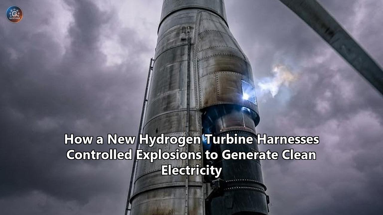
On August 4, 2026, researchers at the Karlsruhe Institute of Technology (KIT) achieved a long-sought milestone in clean energy engineering: operating a compressorless, hydrogen-fueled gas turbine for a record 303 seconds while successfully generating electricity directly from continuous supersonic detonation waves. Led by Professor Daniel Banuti, Director of KIT’s Institute of Thermal Energy Technology and Safety (ITES), the team surpassed NASA’s previous 250-second operational benchmark for rotating detonation hardware, demonstrating that controlled micro-explosions can eliminate the single largest energy drain in gas turbine power generation.
In a conventional gas turbine, a mechanical axial compressor squeezes incoming air to high pressures before fuel injection and combustion. That mechanical compressor consumes approximately 50% of the gross power generated by the turbine, leaving only half the system's total energy output available to drive electrical generators or aircraft propellers.
By shifting from deflagration—the standard sub-sonic burning mechanism—to detonation, the KIT power plant harnesses self-compressing shockwaves that travel around an annular combustion chamber at speeds exceeding 2,000 meters per second. This dynamic, known as pressure gain combustion (PGC), creates high combustion pressure within the chamber itself. The outcome is a self-sustaining thermodynamic process that completely eliminates the mechanical compressor, reclaiming energy losses and fundamentally changing the economics of zero-carbon power generation.
Conventional Gas Turbine (Joule-Brayton Cycle)
[ Air In ] ──> [ Mechanical Compressor ] ──> [ Constant-Pressure Burn ] ──> [ Turbine ] ──> Electricity
                 ▲                                                             │
                 └───────────── Consumes ~50% of Turbine Power ────────────────┘

Detonation Gas Turbine (Pressure Gain Combustion / Humphrey Cycle)
[ Air In ] ──> [ Self-Compressing Detonation Chamber ] ──> [ Pulsed Outflow ] ──> [ Turbine ] ──> Electricity
                 (Supersonic shockwaves compress air internally)                   │
                 (100% of net turbine work preserved) ◄──────────────────────────┘
The achievement comes at a critical juncture for the global power industry. As green hydrogen production scales up, utilities face steep financial penalties if they burn hydrogen through low-efficiency, traditional combustion cycles. Reclaiming the 50% energy loss previously absorbed by mechanical compressors provides a thermodynamic leap forward that could lower the levelized cost of hydrogen-generated electricity.
Deflagration vs. Detonation: Quantitative Thermodynamic Breakthroughs
To understand the magnitude of KIT's 303-second run, consider the thermodynamic metrics that separate traditional gas turbines from pressure-gain systems.
Standard gas turbines operate on the Joule-Brayton cycle, where combustion occurs at constant pressure. Because the chemical reaction pushes expanding gases outward into open space, pressure drops across the combustor, forcing engineers to rely on massive, multi-stage mechanical compressor fans up front.
Pressure gain combustion relying on Rotating Detonation Combustors (RDC) approximates the Humphrey cycle—a thermodynamic process defined by near-constant-volume combustion. Instead of a slow-moving flame front (deflagration) burning at tens of meters per second, a detonation wave sweeps through the compressed fuel-air mixture at Mach 5 to Mach 7. This releases energy so quickly that the expanding gas cannot escape before creating an intense local pressure spike.
+------------------------------------+-----------------------------------+-----------------------------------+
| Metric                             | Standard Joule-Brayton Cycle      | Pressure Gain Detonation Cycle    |
+------------------------------------+-----------------------------------+-----------------------------------+
| Combustion Type                    | Deflagration (Subsonic flame)     | Detonation (Supersonic shockwave) |
| Wave Propagation Speed             | 10 - 50 m/s                       | 1,800 - 2,200 m/s                 |
| Combustor Pressure Delta           | Pressure Loss (-3% to -5%)        | Pressure Gain (+10% to +35%)      |
| Compressor Parasitic Energy Drag   | ~50% of gross work                | 0% (Compressorless configuration) |
| Open-Cycle Efficiency Gain         | Baseline                          | +3.2 percentage points            |
| Combined-Cycle Efficiency Gain     | Baseline (~60-62%)                | +1.8 to +4.0 percentage points    |
| Specific Work Output Boost         | Baseline                          | +67 kJ/kg of air                  |
+------------------------------------+-----------------------------------+-----------------------------------+
Thermodynamic modeling conducted across major power research consortiums shows the concrete performance increases available through this transition:
- Specific Work Output: Open-cycle gas turbines equipped with hydrogen rotating detonation combustors yield an additional 67 kilojoules of work per kilogram of air ($\text{kJ/kg}_{\text{air}}$) compared to conventional designs. In combined-cycle applications, specific work expands by 30 $\text{kJ/kg}_{\text{air}}$.
- Thermal Efficiency Margins: Integrated RDC systems increase open-cycle gas turbine efficiency by 3.2 percentage points. When coupled with a three-pressure-level reheat heat recovery steam generator (HRSG) in a combined-cycle power plant, total system efficiency rises by up to 1.8 to 4.0 percentage points over state-of-the-art baselines.
- Peak Pressure Ratios: While conventional gas turbines require compressor pressure ratios of 30:1 to 40:1 to reach high thermal efficiency, RDC systems achieve equivalent or superior peak pressures natively within the combustor at significantly lower inlet compression demands.
"A conventional gas turbine consumes about 50 percent of its power to compress air to the high pressure needed for efficient combustion," explained Professor Daniel Banuti during the August 2026 announcement. "By generating that pressure natively inside the combustion chamber via fluid mechanical instabilities and shockwaves, we reclaim that lost power entirely for electricity generation."
Shock Wave Kinetics: Fluid Dynamics inside the Annulus
The physics powering the KIT design rely on continuous rotating detonation waves operating inside an annular gap—a narrow ring-shaped channel situated between an inner core and outer casing.
               [ Outer Combustor Casing ]
         ┌─────────────────────────────────────┐
         │   Fresh Fuel/Air Injection (H2+Air) │
         │   │   │   │   │   │   │   │   │     │
  ======>│   ▼   ▼   ▼   ▼   ▼   ▼   ▼   ▼     │=====> High-Pressure
  Inlet  │ ─────────────────────────────────── │       Supersonic Exhaust
  Air    │  ◄── Detonation Wave (2,000 m/s) ── │       to Turbine Blades
         │ ─────────────────────────────────── │
         │   Post-Detonation High-P Region     │
         └─────────────────────────────────────┘
               [ Inner Combustor Core ]
When hydrogen gas and preheated air are injected axially into the annulus, a high-speed ignition establishes a shockwave that travels circumferentially around the ring. As the shockwave races around the channel at 1,800 to 2,200 meters per second, it continuously consumes the fresh fuel-air mixture injected ahead of it.
Immediately behind the shockwave, a steep pressure peak forms, followed by an expansion zone. The ultra-high pressure of the burned gas temporarily blocks fresh fuel injection directly behind the wave. However, as the wave travels past, local pressure drops, allowing fresh hydrogen and air to fill the channel once again just in time for the detonation wave to complete its circuit and ignite the mixture again.
Detonation Front Kinetic Profile
Pressure (MPa)
  ▲
3.0│      /|  <-- Detonation Shock Front (Peak ~2.5 - 3.0 MPa)
2.0│     / |
1.0│    /  |________ Expansion Zone (P drops, allowing re-injection)
0.0└───/────────────► Time / Distance along channel
In the KIT reactor, this cycle repeats at frequencies between 2,000 Hz and 8,000 Hz (2 to 8 kHz). To an observer, the process appears as a steady burn, but internally it consists of thousands of controlled explosions detonating every second.
Operational Predictability and Wave Modes
Transitioning detonation physics from chaotic explosions into predictable utility-grade energy required advanced data science and computational modeling. Research conducted by the U.S. Department of Energy’s National Energy Technology Laboratory (NETL) under Dr. Justin Weber provided foundational analytics that made the KIT run possible.
NETL scientists analyzed 6,702 operational test samples from a water-cooled rotating detonation engine operating under varying hydrogen flow rates, backpressures (up to 2 MPa), and equivalence ratios. Using multi-class machine learning classifiers (XGBoost), NETL proved that detonation wave counts—whether a combustor operates with 2, 3, 4, 5, or 6 simultaneous rotating waves—are entirely deterministic.
NETL Experimental Analytics Matrix
+-----------------------------------------+-----------------------------------+
| Dataset Sample Size                     | 6,702 validated operational runs  |
| Max Test Chamber Pressure               | 2.0 MPa (20 bar)                  |
| Monitored Wave Modes                    | 2, 3, 4, 5, and 6 co-rotating     |
| Predictive Model Accuracy (Validation)  | 96.0% accuracy across unseen data |
+-----------------------------------------+-----------------------------------+
The XGBoost model achieved a 96% prediction accuracy on unseen validation datasets, demonstrating that wave modes depend predictably on four primary variables: backpressure ($P_{\text{back}}$), total mass flow rate ($\dot{m}$), fuel-air equivalence ratio ($\phi$), and preheat mixture temperature ($T_{\text{mix}}$). This predictable behavior allowed engineers to program digital control systems capable of maintaining stable single- and multi-wave modes, preventing destructive acoustic resonance or wave extinction.
Overcoming Thermal and Mechanical Stress
Sustaining continuous detonation without destroying the turbine hardware requires solving extreme thermal management and fluid dynamic challenges. Prior to 2026, experimental detonation combustors were strictly limited to runtimes measured in milliseconds or a few seconds before wall temperatures spiked past material failure limits.
Thermal Resistance Timeline for Experimental Hydrogen Detonation Hardware
Runtime (Seconds)
350 ───────────────────────────────────────────────────────────► 303s (KIT - August 2026)
300 ─────────────────────────────────────────► 251s (NASA MSFC - 2023)
250 ────────────────────────────────
100 ──────────► 90s (AIAA / ITES Water-Cooled RDC - Jan 2026)
  0 └─────────┴──────────┴──────────┴──────────┴──────────┴────
    2020      2022       2023       2024       2025       2026
Three critical engineering interventions enabled KIT to break the 5-minute operational boundary:
1. Active Thermal Management and Water Ingestion
The KIT group employed a closed-loop, water-cooled combustor geometry integrated with downstream water injection. During hot-fire testing with hydrogen mass flows ranging between 1 g/s and 2 g/s, peak gas temperatures inside the detonation zone reached upwards of 1,700°C.
By circulating cooling fluids through the inner core and outer casing walls, and strategically injecting atomized water mist into the exhaust diffuser downstream of the detonation front, the team tempered gas temperatures before the flow contacted the moving turbine blades. This stabilized wall static temperatures, allowing the rig to reach thermal equilibrium after 8 to 10 seconds of operation and continue running indefinitely without melting.
2. Low-Pressure-Drop Aero-Strut Fuel Injectors
A historic hurdle in advancing hydrogen turbine technology has been fuel injector pressure loss. Traditional pintle injectors created high flow resistance, causing significant pressure drops that degraded overall system efficiency.
Conventional Pintle Injector:
Inlet Air ──► [ High Restrictive Flow Channel ] ──► (-15% Pressure Drop) ──► Combustor

NETL Aero-Strut Injector (CFD-Optimized):
Inlet Air ──► [ Streamlined Aero-Profile Struts ] ──► (<5% Pressure Drop)  ──► Combustor
Using high-fidelity computational fluid dynamics (CFD) simulations, researchers designed and validated aerodynamic strut injectors. The aero-strut configuration feeds hydrogen fuel and air into the chamber while dramatically cutting injector pressure drop, preventing premature back-fire into the supply lines while maximizing net pressure gain across the stage.
3. Unsteady Transonic Flow Damping
Because detonation waves produce unsteady, pulsating exhaust flows traveling at transonic speeds, coupling an RDC directly to a traditional rotating turbine shaft often leads to severe mechanical vibration, blade erosion, and aerodynamic stall.
To reconcile these dynamic forces, international research projects like the European Union's H2POWRD program designed specialized diffuser transition zones. Positioned between the combustor exit and the first-stage turbine blades, these diffusers condition the exhaust stream by dampening high-frequency pressure oscillations and leveling Mach number variations. This conditions the pulsed detonation energy into a steady, high-momentum gas stream, allowing conventional turbine blading to convert fluctuating pressure waves into smooth rotation.
Market Projections and Industrial Integration
The breakthrough at KIT arrives as global energy infrastructure accelerates investments in clean dispatchable power. While wind and solar capacity expand worldwide, grid operators require high-efficiency firming generation to maintain system reliability during prolonged renewable generation dunks.
According to market data published in mid-2026, the global market for hydrogen gas turbines reached $1.61 billion to $1.62 billion in 2025/2026 and is projected to expand to $3.47 billion to $3.49 billion by 2032–2034, reflecting a compound annual growth rate (CAGR) of 8.9% to 10.02%.
Global Hydrogen Gas Turbine Market Projection (2025 - 2034)
Market Value ($ USD Billions)
$4.0B ─────────────────────────────────────────────────────────► $3.49B (2034)
$3.5B ───────────────────────────────────────────────────▲
$3.0B ─────────────────────────────────────────────▲
$2.5B ───────────────────────────────────────▲
$2.0B ─────────────────────────────────▲
$1.5B ──► $1.61B (2025)
$1.0B └───┴───────┴───────┴───────┴───────┴───────┴───────┴───────┴───────►
         2025    2026    2027    2028    2029    2030    2032    2034
Market Segmentation by System Configuration
Data reveals a decisive split in equipment demand across the industry:
- Combined-Cycle Systems (56.5% Market Share): Valued at over $910 million in revenue, combined-cycle installations dominate baseload utility orders. Operators prioritizing fuel efficiency leverage steam bottoming cycles to convert waste heat into supplementary electricity, driving net plant efficiency past 60%.
- Open-Cycle Systems (43.5% Market Share): Accounting for the remainder of the market, open-cycle units are favored for rapid-start peaking plants. Their lower capital expenditure (CapEx) and instant start-up response times make them ideal for balancing real-time grid fluctuations.
2025/2026 Hydrogen Gas Turbine Revenue Split
┌──────────────────────────────────────────┬──────────────────────────────────┐
│ Combined-Cycle Power Plants (56.5%)      │ Open-Cycle Peaking Units (43.5%) │
│ High efficiency, baseload power          │ Fast response, low CapEx          │
└──────────────────────────────────────────┴──────────────────────────────────┘
Major original equipment manufacturers (OEMs) report record backlogs for fuel-flexible power equipment. In mid-2026, GE Vernova disclosed that its gas turbine order backlog had expanded to 116 gigawatts (GW), heavily driven by orders for hydrogen-ready HA-class turbines and systems capable of co-firing high hydrogen percentages. Siemens Energy, Mitsubishi Heavy Industries, and Baker Hughes have similarly reported expanding profit margins and multi-billion-dollar backlogs as utilities secure dispatchable capacity.
Economic Viability: Reclaiming Levelized Costs
The principal bottleneck hindering green hydrogen adoption has been fuel cost. Green hydrogen produced via water electrolysis currently costs between $3.50 and $6.00 per kilogram, making it significantly more expensive per gigajoule than natural gas. Burning expensive fuel in a standard turbine where half the energy is lost to mechanical compression creates challenging economics for project developers.
Integrating pressure-gain detonation combustors directly alters this financial equation by improving overall plant efficiency.
Levelized Cost of Electricity (LCOE) Impact Model
Levelized Cost ($/MWh)
 $180 ┌─────────────────────────────────────────┐
 $160 │  Standard Joule-Brayton Hydrogen GT    │  ~$165 / MWh
 $140 │  (50% Compressor Loss)                  │
 $120 ├─────────────────────────────────────────┼─────────────────────────┐
 $100 │                                         │  Pressure-Gain Detonation
  $80 │                                         │  Hydrogen Turbine
  $60 │                                         │  (Compressorless)
  $40 │                                         │  ~$128 / MWh (-22.4%)
  $20 │                                         │
   $0 └─────────────────────────────────────────┴─────────────────────────┘
Consider the financial impact on a baseline 500-megawatt (MW) hydrogen power plant operating at a 65% capacity factor:
- Fuel Consumption Reductions: A 3.2 percentage point jump in efficiency reduces annual hydrogen fuel consumption by approximately 6% to 8% for equivalent power output.
- Capital Expenditure Savings: Eliminating 10 to 15 stages of complex compressor blading lowers the physical footprint, weight, and manufacturing complexity of the gas turbine, reducing machinery CapEx by an estimated 15% to 20%.
- Levelized Cost of Electricity (LCOE): On an unassisted commercial basis, pressure-gain hydrogen turbine technology reduces the LCOE from an estimated $165 per megawatt-hour (MWh) down to approximately $128 per MWh under present fuel pricing, accelerating market parity with fossil-fuel alternatives equipped with carbon capture.
Technical Challenges Facing Full-Scale Deployment
Despite the technical leap represented by KIT’s 303-second continuous generator run, significant technical hurdles remain before multi-hundred-megawatt detonation power plants can connect to commercial grids.
Key Technical Challenges Matrix
┌─────────────────────────────┬─────────────────────────────────┬─────────────────────────────────┐
│ Obstacle                    │ Engineering Cause               │ Mitigation Strategy             │
├─────────────────────────────┼─────────────────────────────────┼─────────────────────────────────┤
│ Extreme Material Fatigue    │ kHz pressure oscillations       │ Advanced single-crystal super-  │
│                             │ and cyclic shock loading        │ alloys and ceramic matrix       │
│                             │                                 │ composites (CMCs)               │
├─────────────────────────────┼─────────────────────────────────┼─────────────────────────────────┤
│ Thermal Nitrogen Oxide      │ Localized peak flame            │ Ultra-lean premixed injection,  │
│ (NOx) Formation             │ temperatures exceeding 1,800°C  │ staged exhaust cooling, and     │
│                             │                                 │ selective catalytic reduction   │
├─────────────────────────────┼─────────────────────────────────┼─────────────────────────────────┤
│ High-Frequency Acoustic     │ Shockwave interaction with      │ Passive acoustic resonators and │
│ Resonance                   │ combustor casing and piping     │ real-time AI closed-loop fuel   │
│                             │                                 │ modulation                      │
└─────────────────────────────┴─────────────────────────────────┴─────────────────────────────────┘
1. High-Cycle Fatigue and Structural Dynamics
Because detonation waves exert periodic mechanical impacts on combustor walls at frequencies reaching several kilohertz, materials undergo millions of high-stress pressure cycles within hours of operation. Standard turbine alloys suffer from accelerated micro-cracking under these conditions. Metallurgists are currently testing single-crystal nickel-based superalloys and ceramic matrix composites (CMCs) capable of enduring high thermal shock loads without structural degradation.
2. Thermal NOx Control
The high temperatures associated with detonation waves (spaking above 1,800°C) accelerate thermal nitrogen oxide ($\text{NO}_x$) formation via the Zeldovich mechanism when burning hydrogen in air. To prevent air pollution penalty spikes, developers are refining ultra-lean premixed injection strategies, steam injection, and advanced downstream selective catalytic reduction (SCR) systems to keep total plant emissions well below regulatory limits.
3. Acoustic Coupling and Grid Integration
The continuous high-frequency noise generated by rotating detonation engines creates intense external acoustic pressure waves. Power plant designs must integrate acoustic dampening structures, sound-absorbing enclosures, and tuned passive resonators to protect balance-of-plant electrical systems and meet industrial noise standards.
Global Scaling Roadmap and Next Steps
The successful demonstration of electricity generation at KIT marks a pivot point, transitioning pressure-gain detonation from theoretical fluid mechanics into applied utility engineering.
Commercial Development Timeline
2023 - 2024: Component Detonation Proofs (NASA 251s RDRE, NETL RDC Rigs)
     │
2026: Success at Scale (KIT 303s Electricity Generation; NETL Aero-Strut Injectors)
     │
2028 - 2029: Pilot Demonstrators (10 MW - 30 MW Class Stationary RDC Turbines)
     │
2032 - 2035: Utility-Scale Deployment (300 MW+ Combined-Cycle Commercial Units)
Several key milestones are slated for the remainder of the decade:
- Utility Demonstration Pilots (2028–2029): Consortiums across Europe, North America, and East Asia are preparing 10 MW to 30 MW class pilot power plants. Industrial deployments like Mingyang Group's 30 MW pure-hydrogen "Jupiter-1" turbine in Inner Mongolia highlight the rapid scaling of high-volume hydrogen power systems.
- Material Wear Benchmarks: Researchers plan to scale operational testing from minutes to multi-hundred-hour continuous validation runs, establishing reliable mean-time-between-failures (MTBF) datasets for commercial warranty standards.
- Next-Generation Integration with Decarbonized Infrastructure: By eliminating parasitic compressor loads, pressure-gain systems will be coupled directly with high-efficiency green hydrogen supply networks, providing dispatchable, zero-emission electricity to industrial grids.
As energy networks balance variable renewable power with dispatchable generation, the ability to extract maximum work from clean hydrogen is essential. By turning violent shockwaves into a continuous energy source, pressure-gain hydrogen turbine technology offers a direct pathway toward zero-carbon power generation.
Reference:
- https://www.sciencedaily.com/releases/2026/08/260803080919.htm
- https://www.autonocion.com/us/hydrogen-turbine-kit-nasa/
- https://www.researchgate.net/publication/396335971_Reaching_90_sec_runtime_throttling_and_turbine_operation_with_a_hydrogen-based_rotating_detonation_combustor
- https://webthesis.biblio.polito.it/34985/1/tesi.pdf
- https://asmedigitalcollection.asme.org/GT/proceedings/GT2025/88803/V004T06A028/1220309
- https://netl.doe.gov/sites/default/files/2025-04/FY25%20Advanced%20Turbines%20Peer%20Review%20Overview%20Report_03312025.pdf
- https://www.miragenews.com/hydrogen-turbine-converts-explosions-to-1721547/
- https://netl.doe.gov/projects/files/GlobalEvaluationofProcessConditionsandCorrespondingWaveModesinaRotatingDetonationEngine_010625.pdf
- https://www.netl.doe.gov/node/15440
- https://www.netl.doe.gov/projects/files/DesignandTestingofaWaterCooledRotatingDetonationCombustoratElevatedOperatingPressures_101221.pdf
- https://arc.aiaa.org/doi/10.2514/6.2026-2922
- https://www.turbomachinerymag.com/view/hydrogen-ready-low-emissions-turbine-technologies-advance-in-2025
- https://cordis.europa.eu/project/id/101169009
- https://www.openpr.com/news/4594998/hydrogen-gas-turbine-market-set-to-hit-us-3-47-billion-by-2032
- https://growthmarketreports.com/report/hydrogen-gas-turbines-market-global-industry-analysis
- https://gasturbinehub.com/oems-recovered-market-responded-what-2025-tells-us-about-gas-turbines-in-2026/