For nearly a century, polytetrafluoroethylene—known globally by its Chemours brand name, Teflon—has served as modern engineering’s ultimate chemical redoubt. Bound together by the carbon-fluorine bond, among the strongest single linkages in organic chemistry at roughly 485 kilojoules per mole, the fluoropolymer resists attacks that dissolve ordinary plastics, shatter ceramics, and pit structural metals. Chemical processing plants line reactive acid tanks with it. Aerospace manufacturers spray it across critical fairings. Automakers and electronics designers deploy it as a thin dielectric shield to keep corrosive moisture away from delicate circuits and copper busbars.
A research team led by physical chemists at the Max Planck Institute for Polymer Research in Mainz, Germany, upended this foundational assumption. In a report published in Nature (DOI: 10.1038/s41586-026-10941-6), lead author Zhongyuan Ni, group leader Rüdiger Berger, and institute director Hans-Jürgen Butt demonstrated that ordinary raindrops, sliding down everyday surfaces like leaves, windowpanes, or plastic panels, pick up static electricity and unleash microscopic electrical arcs upon impact. When striking metal protected by an ultrathin fluoropolymer shield, these tiny electrical discharges deliver a localized voltage spike sufficient to pierce the barrier.
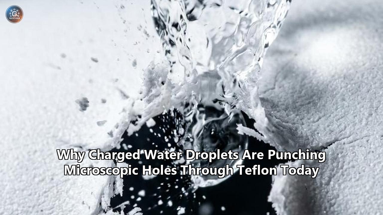
Instead of chemically attacking the polymer chains or physically abrading the surface at high velocity, the drops act as miniature capacitors discharging across a microscopic air gap. They punch pinhole-sized puncture craters directly through the non-conductive film, laying bare the metal underneath to rapid oxidation and pitting. The revelation that sliding raindrops transform into high-voltage lances directly challenges century-old engineering protocols for corrosion prevention, exposing fundamental vulnerabilities in how infrastructure, clean energy hardware, and microelectronics are sealed against the elements.
+-----------------------------------------------------------------------------------+
|               ANATOMY OF A MICRO-LIGHTNING DIELECTRIC PUNCTURE                    |
|                                                                                   |
|  1. Sliding Drop Accrues Charge      2. Taylor Cone Formation                     |
|     (0.2 to 2.0 nC, >1 kV)              (Maxwell stress stretches liquid tip)     |
|                                                                                   |
|         ~~~ (Slide over leaf/PVC)               \  + + +  /                       |
|           \___                                   \ + + + /                        |
|               \  [ + + + Drop ]                   \  +  /                         |
|                \_______                            \ v /  (Tip sharpens)          |
|                                                     ---                           |
|                                                                                   |
|  3. Localized Dielectric Breakdown   4. Chemical Corrosion Pathway Opens          |
|     (E > 60 kV/mm arcing at 10 µm)      (Pinhole exposes substrate to salt/water) |
|                                                                                   |
|             \       /                              \       /                      |
|              \ + + /                                \ H2O /                       |
|               \===/                                  \===/                        |
|            ⚡ Spark Discharge ⚡                       |   |                        |
|     ========\     /======== [Teflon 60 nm]    =======|   |======= [Teflon Film]   |
|     ---------=====---------                   -------[Pit]-------                 |
|     ####################### [Copper Metal]    #####[Cu2O/CuCl2]## [Oxidized Metal]|
+-----------------------------------------------------------------------------------+
The Spark in the Rain: Mechanics of the Microscopic Arc
The experimental work began with an observation that ran counter to conventional fluid mechanics. Physical chemists have known for centuries that rubbing two dry, insulating solid materials together generates static electricity through tribocharging. However, the premise that liquid water sliding across an insulator could mimic solid-state friction electricity was long viewed with skepticism. Classical theory held that the mechanical forces of liquid surface tension were far too weak to overcome atomic bonds and concentrate localized charges.
Over the past decade, that dogma dissolved as surface physicists discovered "slide electrification". When a droplet of water moves across a hydrophobic or dielectric solid, it interacts with the substrate through an electrical double layer (EDL). As the liquid rolls or slides, the shear forces separate the paired charges at the interface. The trailing solid surface retains one polarity, while the moving droplet carries away an uncompensated excess of the opposite polarity.
To test whether this mobile charge carried corrosive consequences, Ni, Berger, Butt, and their collaborators from the University of Bonn, the South China University of Technology, MIT, and Johannes Gutenberg University Mainz constructed a controlled laboratory setup. They introduced individual 35-microliter droplets of water—a volume comparable to large raindrops falling in a summer shower—doped with a minor concentration of sodium chloride to match the ionic salinity of natural atmospheric precipitation.
The droplets were released down a variety of 50-degree inclined surfaces spanning four common outdoor materials:
- A living leaf of an oyster plant (Tradescantia spathacea);
- A commercial polyvinyl chloride (PVC) construction foam board;
- A sheet of polystyrene (PS) window paneling;
- A quartz slide functionalized with perfluorooctadecyltrichlorosilane (PFOTS), a common industrial water-repelling hydrophobic coating.
As the drops slid just four centimeters down these sloping panels, they became electrically charged. Measurements using an electrometer revealed that each droplet accumulated an electrostatic charge ranging from 0.2 to 2.0 nanocoulombs. While a nanocoulomb seems infinitesimally small in bulk electrical engineering, condensing that charge onto a single millimeter-scale droplet creates an electrical potential relative to ground that readily exceeds 1,000 volts, occasionally scaling up to 9,000 volts.
+-----------------------------------------------------------------------------------+
|               MEASURED CHARGE ACCUMULATION ACROSS SLIDING SUBSTRATES              |
+------------------------------+--------------------+-------------------------------+
| Sliding Substrate Material   | Net Droplet Charge | Equivalent Surface Potential  |
+------------------------------+--------------------+-------------------------------+
| Tradescantia Leaf (Foliage)  | ~0.25 to 0.60 nC   | 1.1 kV to 2.8 kV              |
| Rigid PVC Foam Panel         | ~0.80 to 1.40 nC   | 3.5 kV to 6.2 kV              |
| Polystyrene Window Sheet     | ~0.40 to 1.10 nC   | 1.8 kV to 4.9 kV              |
| PFOTS-Coated Hydrophobic Glass| ~1.20 to 2.05 nC   | 5.4 kV to >9.0 kV             |
+------------------------------+--------------------+-------------------------------+
The researchers arranged the test so that after rolling off the inclined plane, each charged droplet dropped five millimeters onto a target: a copper plate shielded by an ultra-thin, 60-nanometer layer of Teflon.
High-speed microscopic video revealed an astonishing dynamic in the final milliseconds before impact. When an electrically neutral drop falls toward a surface, its bottom interface remains rounded and spherical under the stabilizing force of surface tension. But as the charged droplet neared the copper plate, the free electrons within the metal conductor rearranged themselves instantaneously, establishing a powerful "image charge" directly beneath the insulating Teflon coating.
This electrostatic attraction generated massive Maxwell stress along the droplet’s lower boundary, pulling the fluid into a sharply pointed conical structure known as a Taylor cone. As the tip of this conductive, ionized cone narrowed the distance to approximately 10 micrometers above the Teflon barrier, the local electric field ($E$) escalated exponentially:
$$E \approx \frac{V}{d}$$
When the localized field intensity eclipsed 60 kilovolts per millimeter ($60\ \text{kV/mm}$)—the dielectric breakdown strength of Teflon—the air and the polymer failed as insulators.
In a sub-microsecond flash of localized plasma, the drop discharged. Electrometer logging showed that of a 2.0-nanocoulomb charge, roughly 1.8 nanocoulombs surged straight through the fluoropolymer barrier into the copper substrate below, leaving behind less than 0.016 nanocoulombs in the fluid that bounced away. The dielectric breakdown unleashed localized thermal and electrostatic forces that physically vaporized nanoscale channels through the Teflon film.
"When such charged droplets strike a coating, they discharge locally and can puncture the layer in specific spots like a small flash of lightning," explained Rüdiger Berger, head of the Physics at Interfaces department at the Max Planck Institute. The damage was not caused by mechanical cavitation or acidic dissolution, but by an electrical insulation failure operating at the scale of nanometers.
Direct Impacts vs. Sliding Runs: The Control That Upended Corrosion Science
The central breakthrough in the Mainz investigation was not merely documenting that water droplets pick up static electricity, but proving conclusively that electrical discharge—not kinetic impact or fluid chemistry—initiates the destruction of the barrier film.
Early in the testing, the destructive mechanism almost escaped notice. Zhongyuan Ni initially subjected the Teflon-coated copper plates to hundreds of falling drops without observing any measurable degradation under optical inspection.
"At first, it was not clear whether these electrified drops caused damage," Ni recounted. "In early experiments, I could find no damage to a surface after hundreds of drops. One day, I just let the experiment keep running. I went to drink coffee or something. When I came back, after thousands of drops, it looked like the drops were pinning onto the surface".
+-----------------------------------------------------------------------------------+
|               CONTROL VS. CHARGED IMPACT COMPARISON (3,000 CYCLES)                |
+--------------------------+----------------------------+---------------------------+
| Operational Metric       | Neutral Droplet Control    | Slide-Electrified Droplet |
+--------------------------+----------------------------+---------------------------+
| Pre-Impact History       | Direct syringe drop        | Slid 4 cm down 50° incline|
| Net Droplet Charge       | 0.00 ± 0.01 nC             | 1.80 ± 0.22 nC            |
| Impact Geometry          | Smooth, spherical base     | Pointed Taylor cone tip   |
| Dielectric Stress        | 0 kV/mm (No arc)           | >60 kV/mm (Local arc)     |
| Surface Morphology (AFM) | Smooth, root-mean-square   | Perforated by pits tens of|
|                          | roughness unchanged        | nanometers deep           |
| Copper Substrate State   | Pristine, 100% protected   | Oxidized; chemical pits   |
| Electrochemical Barrier  | Intact; high impedance     | Ruptured; rapid leakage   |
+--------------------------+----------------------------+---------------------------+
To isolate the electrostatic variable, the researchers designed an airtight control experiment. They positioned the droplet dispenser directly above the Teflon-coated copper, allowing identical 35-microliter saltwater droplets to fall the exact same distance without contacting any inclined insulating substrate. These neutral droplets struck the 60-nanometer Teflon barrier 3,000 times at identical 12-second intervals.
Atomic force microscopy (AFM) and confocal laser scanning revealed that the neutral droplets left the Teflon completely unblemished. The surface roughness showed no mechanical wear, no thinning, and no microscopic pitting. Chemically, the underlying copper showed no signs of reaction. Despite the saline chemistry and thousands of kinetic strikes, the non-stick polymer had done its job: it repelled the water and blocked ionic transmission.
The results were completely different when the droplets were allowed to slide down a leaf or a piece of PVC before landing on the target. After 3,000 impacts from these slide-electrified droplets, the Teflon coating was perforated with crater-like pits extending completely through the 60-nanometer polymer layer.
The experiments tracking charged water droplets teflon degradation patterns revealed a rapid, self-reinforcing failure cycle. The instant dielectric breakdown punched a microscopic hole through the fluoropolymer, the barrier was breached. Saline water immediately seeped into the nanoscale void, making direct physical and electrical contact with the copper plate.
+-----------------------------------------------------------------------------------+
|                     PROGRESSION OF CAPILLARY-ARC CORROSION                        |
|                                                                                   |
|  Drops 1 - 500:       Elastic impacts; minor charge accumulation in polymer bulk. |
|  Drops 500 - 3,000:   Local field breaches 60 kV/mm; dielectric punch-through.    |
|  Drops 3,000 - 10,000: Saline ingress; copper barrier impedance collapses.        |
|  Drops 10,000 - 50,000: Self-accelerating pitting; Cu2O & Cu2(OH)3Cl bloom >1 mm.  |
+-----------------------------------------------------------------------------------+
As the exposure continued, the degradation accelerated sharply:
- At 10,000 charged impacts, electrochemical impedance spectroscopy demonstrated that the Teflon coating's protective barrier properties had collapsed entirely. The plate suffered worse degradation than an identical sample submerged continuously in bulk saltwater for four hours—the cumulative contact time of all 10,000 droplets combined.
- At 50,000 impacts, the microscopic perforations merged into wide corrosion zones exceeding one millimeter in diameter, easily visible to the naked eye.
To confirm the chemical nature of the metal damage beneath the pierced film, collaborator Shuai Chen at the University of Bonn conducted powder X-ray diffraction (PXRD) measurements. The diffraction patterns detected high concentrations of cuprous oxide ($Cu_2O$) and basic copper chloride ($Cu_2(OH)_3Cl$, or atacamite). The dielectric sparks had opened direct pathways through the inert polymer, allowing atmospheric oxygen and dissolved chlorine ions to consume the unprotected copper beneath.
The team also tested whether droplet flight was strictly required to induce this breakdown. In a lateral experiment, they deposited a continuous Teflon film across a split substrate made of half-quartz (an electrical insulator) and half-copper (an electrical conductor). When saline droplets simply slid across the surface, moving from the quartz side toward the copper side, the sudden shift in image charge generated localized discharges right at the buried material boundary. After 3,000 passes, a sharp, trench-like fissure had been carved straight through the Teflon along the boundary seam. Sliding alone, without any dropping or splashing, was enough to blow apart the coating.
Three Paradigms of Degradation: Mechanical, Chemical, and Dielectric
For over a century, materials engineers and corrosion scientists modeled surface weathering through two primary frameworks: mechanical wear and electrochemical corrosion. The Max Planck Institute’s findings introduce an unmodeled third vector: electro-dielectric puncture.
+-----------------------------------------------------------------------------------+
|               COMPARING THE THREE DOMINANT SURFACE DAMAGE MODES                   |
+-------------------+-----------------------+-------------------+-------------------+
| Dimension         | 1. Mechanical Erosion | 2. Chemical Attack| 3. Dielectric Arc |
+-------------------+-----------------------+-------------------+-------------------+
| Primary Driver    | Kinetic momentum &    | Solute diffusion, | Electrostatic     |
|                   | water hammer pressure | galvanic couples, | charge buildup &  |
|                   | ($P = \rho C v$)      | redox reactions   | localized plasma  |
+-------------------+-----------------------+-------------------+-------------------+
| Typical Threshold | Impact velocities     | Permeation rates, | Electric field    |
|                   | $>50\ \text{m/s}$     | chemical acidity, | exceeding         |
|                   | (high Reynolds)       | environmental pH  | $E_{\text{break}}|
+-------------------+-----------------------+-------------------+-------------------+
| Initial Failure   | Fatigue microcracks,  | Matrix swelling,  | Sub-microsecond   |
| Morphology        | delamination, shear   | bond hydrolysis,  | vertical pinhole  |
|                   | chipping              | pitting blisters  | vapor channels    |
+-------------------+-----------------------+-------------------+-------------------+
| Water Velocity    | Very High             | Static or Low     | Gentle / Gravity  |
| Dependency        | ($>180\ \text{km/h}$) | (Stagnant pools)  | ($<15\ \text{km/h}$)|
+-------------------+-----------------------+-------------------+-------------------+
| Influence of Leaf | None (Negligible      | Modest (Alters    | Extreme (Drives   |
| / Plastic Runoff  | kinetic impact)       | droplet acidity)  | high-voltage      |
|                   |                       |                   | electrification)  |
+-------------------+-----------------------+-------------------+-------------------+
| Standard Testing  | ASTM G73 Liquid       | ASTM B117 Salt    | None exist;       |
| Protocols         | Impingement Rig       | Spray Chamber     | blind to static   |
|                   |                       |                   | charge mechanisms |
+-------------------+-----------------------+-------------------+-------------------+
The Mechanical Paradigm
Mechanical water droplet erosion (WDE) occurs when high-velocity liquid droplets smash into a solid surface, generating shockwaves and a rapid deceleration pressure spike known as water hammer pressure:
$$P_{wh} = \rho C v$$
Here, $\rho$ is the liquid density, $C$ is the speed of sound within the droplet, and $v$ is the impact velocity.
Governed by testing standards such as ASTM G73, mechanical erosion dominates in extreme environments: aviation radomes flying through storm cells, steam turbine blades spinning at thousands of revolutions per minute, and offshore wind turbine tips sweeping the sky at 90 meters per second.
Under low-velocity conditions—such as gentle rainfall dripping from roof eaves or foliage at 2 to 5 meters per second—the water hammer pressure drops below the elastic limit of fluoropolymers. Mechanically, the polymer sustains no microcracking or plastic deformation. Engineering models therefore assume that low-speed dripping causes zero structural wear.
The Chemical Paradigm
The electrochemical framework assumes that degradation requires a conductive chemical path. Corrosion engineers evaluate barrier films using standards like ASTM B117 (salt spray fogging) or ISO 9227. These tests measure how quickly corrosive water, oxygen, and salt ions migrate through microscopic pinholes or diffuse through the polymer's free volume.
Because fluoropolymers feature tight packing and non-polar, exceptionally inert carbon-fluorine bonds, their diffusion rates for water and electrolytes are among the lowest of any polymer class. Teflon resists acids, bases, and organic solvents across an operating range of -200°C to +260°C. In the absence of an existing structural defect, pure chemical corrosion across a pristine Teflon barrier requires years, if not decades, to develop.
The Electro-Dielectric Paradigm
The phenomenon unmasked in Mainz bypasses both kinetic energy limits and chemical resistance entirely. In this mode, the droplet does not need high velocity to damage the surface, nor does it require aggressive acids to dissolve the coating.
Instead, the water droplet serves as a mobile electrostatic accumulator. The damage is governed by dielectric physics rather than chemical thermodynamics or mechanical shear:
   Sliding Motion -> Interfacial Charge Separation -> Taylor Cone Formation
        -> Local Field Concentration -> Dielectric Breakdown Arc
             -> Nanoscale Barrier Perforation -> Accelerated Chemical Ingress
The critical vulnerability is that a 60-nanometer layer of Teflon, while chemically unreactive, is thin enough that an electrical potential of just 1,000 volts creates an immense electric field across it. The resulting dielectric puncture vaporizes a vertical channel straight through the polymer. Once this electrical breakdown occurs, classical chemical corrosion takes over, attacking the exposed substrate through the fresh micro-void.
Crucially, standard weathering chambers—such as salt fog cabinets and rain impact simulators—ground their spray nozzles and run water through metal piping. This discharges the fluid before it ever hits the sample. Consequently, these standardized testing environments have been completely blind to this electro-dielectric failure mode for decades.
Evaluating Countermeasures: Four Competing Engineering Strategies
With the discovery that charged water droplets teflon barriers experience localized dielectric failure, the materials science community faces an urgent engineering challenge. How can protective coatings prevent these electrical micro-arcs without compromising their mechanical, thermal, or anti-adhesive performance?
Four competing strategies are now under intense examination across industrial and academic labs, each presenting stark engineering tradeoffs.
+-----------------------------------------------------------------------------------+
|               TRADE-OFF MATRIX OF COMPETING DEFENSE TECHNOLOGIES                  |
+----------------------+--------------------+-------------------+-------------------+
| Engineering Strategy | Core Advantage     | Critical Tradeoff | Primary Failure   |
|                      |                    |                   | Mechanism         |
+----------------------+--------------------+-------------------+-------------------+
| 1. Bulk Dielectric   | Eliminates arcs by | Adds mass, chokes | Delamination;     |
|    Thickening        | lowering E-field   | heat transfer,    | internal fatigue  |
|    (d > 100 µm)      | ($E = V / d$)      | degrades flex     | cracking          |
+----------------------+--------------------+-------------------+-------------------+
| 2. Conductive Carbon | Bleeds static      | Opacity, high     | Catastrophic      |
|    / MXene Additives | charge to ground   | cost, galvanic    | galvanic couple   |
|                      | before breakdown   | corrosion risk    | if breached       |
+----------------------+--------------------+-------------------+-------------------+
| 3. SLIPS Lubricant-  | Prevents solid-    | Vulnerable to UV, | Lubricant washout |
|    Infused Surfaces  | liquid charge      | shear stripping,  | under high-speed  |
|                      | separation         | chemical leach    | rain impacts      |
+----------------------+--------------------+-------------------+-------------------+
| 4. Micro-Engineered  | Preserves pristine | Extreme litho     | Grounding breaks; |
|    Grounding Grids   | dielectric polymer | complexity and    | localized field   |
|                      | chemistry          | manufacturing cost| hotspots at seams |
+----------------------+--------------------+-------------------+-------------------+
Strategy 1: Bulk Dielectric Thickening (Passive Voltage Suppression)
The most straightforward remedy is simply applying a thicker coating of the dielectric material. Because the electric field strength ($E$) equals voltage divided by thickness ($V/d$), increasing the distance between the charged water droplet and the conductive metal plate dilutes the electrostatic gradient.
The Max Planck team proved the viability of this brute-force approach in subsequent trials with polystyrene films. While a 12-micrometer polystyrene film was repeatedly punctured by charged droplets, increasing the film thickness to 130 micrometers suppressed the internal field below the breakdown threshold. The 130-micrometer coating survived 3,000 impacts from electrified droplets without suffering a single dielectric failure or substrate pit.
Dielectric Breakdown Threshold vs. Coating Thickness
---------------------------------------------------------------------------
Coating Thickness (d):   60 nm      12 µm      50 µm     130 µm
Field Intensity (E):    Extremely   Breaches   Marginal   Below
                        High        Limit      Zone       Breakdown
Result Under Drop Arc:  Punctured   Punctured  Pitted     Intact
---------------------------------------------------------------------------- The Tradeoffs:
While thickening works in simple static structures, it poses severe engineering penalties in dynamic applications. Adding 100 or more micrometers of a dense fluoropolymer increases parasite weight, which is unacceptable in aerospace structures and electric vehicles striving for range efficiency.
Furthermore, fluoropolymers exhibit notoriously poor thermal conductivity ($k \approx 0.25\ \text{W/(m}\cdot\text{K)}$). Thickening a protective layer over electronics, battery enclosures, or heat exchangers traps heat, risking catastrophic thermal throttling.
Thicker polymer coatings also generate significant internal stress during thermal cycling, making them prone to crazing, micro-cracking, and delamination.
Strategy 2: Electrically Conductive and Static-Dissipative Composites
Instead of blocking the electric field through thick insulation, an alternative approach incorporates conductive nanoscale fillers into the polymer matrix. By embedding networks of single-walled carbon nanotubes (CNTs), graphene nanoplatelets, or two-dimensional transition metal carbides and nitrides (MXenes), materials scientists can tune the coating's surface resistivity into the static-dissipative window ($10^6$ to $10^9\ \Omega/\text{sq}$).
When a charged water droplet lands on a static-dissipative coating, the accumulated electrons bleed harmlessly to an electrical ground within microseconds, dissipating the energy well before the field reaches the 60 kV/mm threshold required for dielectric breakdown.
- The Tradeoffs:
Conductive additives introduce severe electrochemical vulnerabilities. If a carbon-doped fluoropolymer coating suffers a physical scratch that reaches the underlying metal, the conductive carbon network forms a direct galvanic couple with the metal substrate. In the presence of saltwater, carbon acts as a massive cathode while the metal acts as an anode, accelerating galvanic corrosion at rates ten to fifty times faster than ordinary oxidation.
Additionally, carbon and MXene fillers darken coatings to an opaque black or dark gray, ruling them out for optical components, sensor domes, vehicle clearcoats, or architectural glass.
Strategy 3: Wetting Modulation via SLIPS vs. Superhydrophobic Air Plastrons
A third approach seeks to prevent slide electrification at the interface using advanced surface chemistry and micro-texturing.
+-----------------------------------------------------------------------------------+
|               SUPERHYDROPHOBIC (CASSIE) VS. SLIPS LUBRICANT MATRIX                |
|                                                                                   |
|  Superhydrophobic Micro-Pillars          Slippery Liquid-Infused (SLIPS)          |
|                                                                                   |
|         [ Water Droplet ]                        [ Water Droplet ]                |
|             o o o o                                  ~~~~~~~~~                    |
|          =============                            =================               |
|          |   |   |   |   (Air Pockets)            |*~*~*~*~*~*~*~*| (PFPE Oil)    |
|          +---+---+---+                            +---------------+               |
|      High friction slide;                    Zero solid-liquid shear;             |
|      Can AMPLIFY charge separation.          Eliminates contact electrification.  |
+-----------------------------------------------------------------------------------+
Engineers historically relied on superhydrophobic surfaces designed around the Cassie-Baxter wetting state, where microscopic pillars trap air pockets beneath a droplet, allowing it to bead up and roll away effortlessly.
However, recent studies show that when droplets roll across solid micro-pillars, the continuous solid-liquid contact actually accelerates slide electrification, producing higher electrostatic charges than flat surfaces. Furthermore, falling raindrops with high kinetic energy can trigger a Cassie-to-Wenzel transition, forcing water down between the pillars, pinning the droplet, and concentrating charge directly at the roots of the microstructures.
To solve this, researchers are turning to Slippery Liquid-Infused Porous Surfaces (SLIPS). Pioneered at Harvard University, SLIPS locks a thin film of chemically inert fluorinated lubricant (such as perfluoropolyether oil) inside a micro-porous polymer sponge.
When a water droplet slides across a SLIPS surface, it glides on a molecular film of liquid oil rather than contacting a solid dielectric lattice. Because charge separation relies on solid-liquid shear across an electrical double layer, SLIPS coatings suppress slide electrification almost entirely.
- The Tradeoffs:
SLIPS systems suffer from rapid lubricant depletion. Under outdoor conditions, wind shear, falling rain, and sunlight steadily strip the lubricating oil away. Once the oil washes out, the bare porous matrix acts as a sponge for moisture, salts, and airborne dirt, accelerating both electrostatic and chemical degradation.
Strategy 4: Micro-Engineered Grounding Meshes and Active Neutralization
The fourth approach decouples the chemical barrier from the electrical grounding system. Instead of altering the fluoropolymer's chemistry, engineers place a microscopic, conductive grounding grid—such as photolithographically patterned gold, copper, or titanium meshes—just beneath the fluoropolymer surface or within a layered composite skin.
This grid connects directly to the vehicle chassis, airframe, or structural steel earth ground. As an electrified droplet nears the surface, the image charge is diverted through the conductive mesh, preventing high fields from concentrating across the dielectric barrier. In stationary installations, this can be paired with passive atmospheric ionizers that deploy low-current corona wires to neutralize charges in falling runoff before the water hits critical components.
- The Tradeoffs:
This strategy carries steep manufacturing and maintenance hurdles. Fabricating fine, conductive micro-grids across compound curves—such as wind turbine blades, aircraft cowlings, or architectural facades—dramatically escalates production costs.
Worse, if mechanical vibration, cyclic aerodynamic loading, or thermal expansion snaps a single grounding trace, the disconnected grid wire becomes an isolated electrical island. Instead of bleeding static electricity away, the broken wire acts as an electrostatic collector, intensifying local field gradients and triggering the very dielectric breakdown it was designed to prevent.
Material Vulnerabilities: Why Teflon's Dielectric Strength Proved Its Undoing
The discovery that charged water droplets teflon layers can rupture forces a fundamental reexamination of why fluoropolymers fail under electrostatic conditions that other materials can sometimes endure.
Teflon’s extreme vulnerability stems from an ironic intersection of its molecular strengths and electrical limits. Polytetrafluoroethylene consists of a linear backbone of carbon atoms completely wrapped in a dense sheath of fluorine atoms. Because fluorine is the most electronegative element, it pulls electron density tightly toward itself, leaving the molecule non-polar, exceptionally inert, and chemically stable.
+-----------------------------------------------------------------------------------+
|                  COMPARATIVE PROPERTIES OF BARRIER DIELECTRICS                    |
+--------------------------+--------------------+-------------------+---------------+
| Material                 | Relative           | Dielectric        | Dominant      |
|                          | Permittivity (εr)  | Strength (kV/mm)  | Vulnerability |
+--------------------------+--------------------+-------------------+---------------+
| Polytetrafluoroethylene  | 2.1                | 60                | Low εr; rapid |
| (PTFE / Teflon)          |                    |                   | localized arc |
+--------------------------+--------------------+-------------------+---------------+
| Polystyrene              | 2.5                | 20                | Low breakdown |
| (PS Polymer)             |                    |                   | threshold     |
+--------------------------+--------------------+-------------------+---------------+
| Silicon Dioxide          | 3.9                | 1,000             | Brittle;      |
| (SiO2 Glass / Quartz)    |                    |                   | microcracking |
+--------------------------+--------------------+-------------------+---------------+
| Polyurethane             | 4.5 to 6.5         | 35                | Hydrolytic    |
| (Aliphatic Clearcoat)    |                    |                   | degradation   |
+--------------------------+--------------------+-------------------+---------------+
| Diamond-Like Carbon      | 5.0 to 8.0         | 700               | Pinholes and  |
| (DLC Thin Film)          |                    |                   | high cost     |
+--------------------------+--------------------+-------------------+---------------+
However, that same symmetry and non-polarity gives Teflon a remarkably low relative permittivity ($\varepsilon_r \approx 2.1$). When a dielectric material with a low dielectric constant is placed in an intense electric field, it cannot easily polarize to dissipate or redistribute the electrical stress.
Consequently, the electrostatic energy generated by an approaching, charged droplet remains tightly focused over a nanometer-scale contact footprint. When the localized field exceeds the material's dielectric strength ($60\ \text{kV/mm}$), the electric field rips electrons directly from the fluoropolymer chains, igniting a microscopic electron avalanche.
The team at the Max Planck Institute demonstrated that this vulnerability extends beyond Teflon to other thin dielectric coatings:
- Polystyrene coatings, which have a lower dielectric breakdown strength of roughly $20\ \text{kV/mm}$, failed at even lower charge thresholds when applied as thin films.
- Applying polystyrene over gold substrates produced the same characteristic puncture craters, proving that the arcing phenomenon does not depend on chemical reactions with copper.
- Even inorganic barriers, such as thin silicon dioxide ($SiO_2$) films deposited over gold, showed localized electrical breakdown when struck by slide-electrified droplets.
While glass-like materials like $SiO_2$ boast much higher intrinsic dielectric breakdown limits (up to $1,000\ \text{kV/mm}$), their structural rigidity and micro-porosity make thin inorganic films vulnerable to pinhole defects that concentrate electric fields.
Teflon's unique danger is that engineers often apply it in extremely thin layers precisely because its chemical resistance is so high. A coating just 50 to 100 nanometers thick easily stops chemical fumes, oxygen, and liquid acids. Yet that same nanometer profile leaves the polymer defenseless against the kilovolt potentials carried by moving water droplets, allowing electrostatic arcs to punch through its defenses.
Industrial and Infrastructure Casualties: Real-World Fallout
The discovery that sliding water droplets can electrically punch through protective barriers exposes widespread vulnerabilities across multiple major industries. In many real-world environments, water rarely falls as isolated, uncharged droplets; it routinely cascades across leaves, plastic trim, fiberglass panels, and painted surfaces before dripping onto metal structures.
+-----------------------------------------------------------------------------------+
|              FIELD ENVIRONMENTS EXPOSED TO DROPLET ARC PUNCTURE                   |
+----------------------+-----------------------------+------------------------------+
| Industry Sector      | Runoff / Charging Source    | Impacted Dielectric Barrier  |
+----------------------+-----------------------------+------------------------------+
| Wind Energy          | Water sliding over glass-   | Polyurethane & fluoropolymer |
|                      | epoxy blade aerofoils       | leading edge protection (LEP)|
+----------------------+-----------------------------+------------------------------+
| Autonomous Vehicles  | Rain cascading off plastic  | Hydrophobic non-stick coatings|
| & Transportation     | windshields & roof trim     | on LiDAR, camera & radar pods|
+----------------------+-----------------------------+------------------------------+
| Semiconductor        | Ultra-pure deionized water  | PFA & PTFE internal lining   |
| Manufacturing        | flowing through Teflon pipes| of chemical delivery tubing  |
+----------------------+-----------------------------+------------------------------+
| Heritage Structures  | Storm runoff dripping from  | Protective organic lacquers  |
| & Architecture       | foliage, awnings, and eaves | on copper domes, monuments   |
+----------------------+-----------------------------+------------------------------+
Wind Turbine Leading Edge Protection (LEP)
One of the most immediate points of exposure is the renewable energy sector, specifically offshore wind turbine blades. The leading edges of modern turbine blades, which sweep through maritime rain at tip speeds exceeding 300 kilometers per hour, are shielded with specialized polyurethane tapes and fluoropolymer barriers.
For years, wind farm operators have observed that blade coatings erode much faster than predicted by kinetic rain impact models. Field inspectors frequently find micro-pitting on blade sections operating at speeds well below the theoretical threshold for mechanical water hammer erosion.
The Max Planck Institute’s findings provide the missing puzzle piece. As rain hits the broad, non-conductive fiberglass-epoxy shell of the blade, droplets slide across the composite skin, accumulating kilovolts of static electricity via slide electrification. When this charged runoff cascades over the leading-edge protection tapes, it releases a continuous barrage of micro-discharges, puncturing the polymer shield.
Once these electrical pinholes breach the tape, high-velocity maritime air and salty mist force their way in, causing delamination and accelerating costly structural damage.
Autonomous Vehicles and Transportation
Modern autonomous and electric vehicles rely heavily on forward-facing LiDAR apertures, optical cameras, and radar radomes. These sensors are routinely treated with fluoropolymer coatings to ensure rain beads up and blows away, keeping the sensor's field of view clear.
In real-world driving conditions, rain rolls down polycarbonate roofs, acrylic windshield moldings, and plastic headlamp housings before dripping onto sensor housings and painted metal hoods. As these charged droplets strike fluoropolymer-coated surfaces, localized electrical discharges can pit the thin protective coatings.
Over time, this micro-pitting causes optical haze on sensor windows, scattering laser pulses and camera imagery. On coated metal body panels, these punctures breach the clearcoat, sparking localized rust spots that seem to appear out of nowhere on modern, high-end vehicles.
Runoff Path on Vehicle Hood:
[Polycarbonate Windshield] ---> (Water Slides & Charges: ~1.5 nC)
     ---> [Drips onto Painted Aluminum/Steel Hood]
          ---> (Dielectric Micro-Arc Punctures Clearcoat)
               ---> (Salt Fog Initiates Under-Film Corrosion)
Semiconductor Cleanrooms and Ultra-Pure Fluidics
The semiconductor manufacturing industry depends on polytetrafluoroethylene (PTFE) and perfluoroalkoxy (PFA) tubing to handle aggressive wet-etch chemicals and ultra-pure water (UPW). Ultra-pure water has near-zero ion content and an extremely high electrical resistivity ($18.2\ \text{M}\Omega\cdot\text{cm}$), making it an exceptional charging fluid under laminar flow.
As ultra-pure water streams through fluoropolymer tubing, it strips charges from the inner wall via streaming electrification. If the piping runs past grounded metal chassis or metallic valve fittings, the resulting potential difference can cause dielectric breakdown arcs directly through the tubing wall.
These micro-arcs not only risk hazardous chemical leaks, but they also blast sub-micron fluoropolymer fragments into the fluid stream. In a advanced semiconductor fabrication plant, a single shed Teflon nanoparticle can land on a silicon wafer, ruining an entire batch of microprocessors.
Architectural Preservation and Cultural Heritage
Outdoor cultural monuments, historic copper domes, and structural landmarks like the Eiffel Tower are frequently coated with organic polymers and waxes to prevent oxidation and green patina formation.
Yet conservators often find severe pitting on metal surfaces sheltered beneath trees, building eaves, or plastic awnings—locations protected from direct, driving rain.
The Mainz study explains this apparent paradox. Water droplets that roll gently down plant foliage, stone facades, or plastic gutters accumulate static charges of several kilovolts. As this runoff slowly drips onto coated bronze or copper structures below, the electrified drops repeatedly discharge into the metal, blasting through protective lacquers and triggering localized corrosion.
Overhauling Testing Standards and Future Research Frontiers
The discovery of droplet-induced dielectric puncture exposes a significant blind spot in materials testing: current international standards for evaluating corrosion and weathering are poorly suited for catching static-driven failure modes.
For decades, the standard protocols for qualifying industrial coatings—including ASTM B117 (salt spray testing), ISO 12944 (paints and varnishes for steel structures), and ASTM G73 (liquid impingement erosion)—have operated under the assumption that corrosion is either purely electrochemical or strictly mechanical. None of these testing regimes account for the electrostatic charge carried by the water droplets themselves.
Traditional Testing Standards vs. Real-World Physics
---------------------------------------------------------------------------------
Testing Standard       Fluid Delivery Setup            Electrical State
---------------------------------------------------------------------------------
ASTM B117 Salt Fog     Metallic nozzles, grounded      Zero net charge (Neutral)
ASTM G73 Liquid Rig    High-speed grounded jet         Zero net charge (Neutral)
Real-World Rainfall    Runoff over leaves, PVC, glass  0.2 to 2.0 nC (>1 kV charge)
---------------------------------------------------------------------------------
Result: Industrial testing chambers pass coatings that fail rapidly in the field.
---------------------------------------------------------------------------------
Because laboratory testing rigs deliver water through grounded metal pipes and atomizing nozzles, test droplets are stripped of static charge before they ever strike the target.
Consequently, thin fluoropolymer coatings earn top marks in laboratory salt spray chambers, surviving thousands of hours of exposure to neutral saltwater fog without showing a single pit. Yet when deployed in the field—where water routinely slides down leaves, roof panels, or composite cowlings—the coatings are bombarded by electrified droplets that puncture the barrier in a fraction of that time.
International standards organizations, including ASTM International and ISO committees, are now facing calls to establish a new category of environmental testing: Electro-Dielectric Liquid Exposure (EDLE). Future compliance standards must require testing materials against water droplets carrying controlled electrostatic charges ranging from 0.1 to 5.0 nanocoulombs.
Meanwhile, materials scientists and surface physicists are pursuing several critical research priorities:
- Mapping Charge Yields Across Real-World Materials
Researchers are working to catalog the precise charging dynamics of everyday surfaces. The Max Planck experiments revealed that a droplet's charge can vary by more than a factor of ten depending on the material it slides across. Systematic testing is now underway to map the triboelectric charging series for outdoor building materials, architectural paints, automotive plastics, and common agricultural vegetation.
- Decoupling Contact-Electro-Catalysis from Dielectric Arcing
Scientists are working to isolate the relative contributions of physical dielectric arcing versus contact-electro-catalysis. First documented in 2022, contact-electro-catalysis occurs when electrons transferred during solid-liquid contact generate reactive oxygen species—such as hydroxyl radicals ($\cdot\text{OH}$) and hydrogen peroxide ($H_2O_2$)—directly at the water's surface. Researchers are investigating whether these short-lived chemical radicals actively cleave the carbon-fluorine bonds of fluoropolymers during impact, acting in concert with the electrical discharges.
- Designing Self-Dissipating Metamaterials
Materials labs are racing to develop multifunctional coatings that combine high dielectric breakdown resistance with self-dissipating surface properties. One promising avenue involves gradient-permittivity nanocomposites, which blend non-stick fluoropolymer outer surfaces with zwitterionic or ionic-liquid-doped interlayers. These engineered layers can safely diffuse localized electric fields to a ground plane before the voltage reaches the dielectric breakdown threshold of the non-stick skin.
The realization that mundane raindrops can become high-voltage lances capable of piercing Teflon changes how surface scientists understand the boundary between liquids and solids. Water is not just a solvent or a blunt mechanical mass; it is an active electrostatic agent capable of generating its own microscopic lightning strikes. As research continues, the engineering world must adapt to a surprising new reality: keeping the elements out requires protecting surfaces not just from the chemistry of the water, but from the hidden electrical sparks it leaves behind.
Reference:
- https://pubmed.ncbi.nlm.nih.gov/42649289/
- https://science.slashdot.org/story/26/09/01/0043208/electrically-charged-raindrops-can-corrode-cars-and-buildings
- https://www.mpg.de/26970422/corrosion-via-charged-droplets
- https://physicsworld.com/a/sliding-water-droplets-corrode-coated-metals/
- https://hackaday.com/2026/09/06/how-charged-water-drops-induce-corrosion/
- https://www.earth.com/science/water-drops-can-unleash-tiny-electrical-discharges-that-trigger-corrosion/
- https://xenospectrum.com/en/charged-raindrops-cause-dielectric-breakdown-corrosion/
- https://autopostglobal.com/latest-scoops/photo-report/article/123782/
- https://www.rdworldonline.com/droplets-get-a-charge-out-of-jumping/
- https://www.semanticscholar.org/paper/Triboelectrification-Induced-Large-Electric-Power-a-Kwak-Lin/0f206db01a1dd2055371d69bc161702ff7c4f933
- https://www.facebook.com/Friendshipness/posts/rain-does-not-wear-metal-down-only-by-impact-or-acid-new-work-from-the-max-planc/1656741285812850/
- https://xenospectrum.com/en/charged-raindrops-cause-dielectric-breakdown-corrosion/
- https://www.thebrighterside.news/post/scientists-discover-why-rain-drops-can-damage-metal-protective-coatings/
- https://www.sciencenews.org/article/corrosion-water-droplets-charge
- https://www.brighton-science.com/blog/how-to-bond-ptfe-to-anything
- https://www.researchgate.net/publication/335597615_Tribochemical_Degradation_of_Polytetrafluoroethylene_in_Water_and_Generation_of_Nanoplastics
- https://pubmed.ncbi.nlm.nih.gov/38584396/
- https://www.zmescience.com/science/chemistry/raindrops-can-build-an-electrical-charge-strong-enough-to-corrode-metal-in-a-surprising-way/
- https://www.teflon.com/en/industries-and-solutions/industries/semiconductor-manufacturing/etching
- https://eureka.patsnap.com/report-analyzing-ptfe-powered-droplet-manipulation-in-lab-on-chip-devices
- https://www.researchgate.net/publication/379662916_Spontaneous_Degradation_of_the_Forever_Chemicals_Perfluoroalkyl_and_Polyfluoroalkyl_Substances_PFASs_on_Water_Droplet_Surfaces