
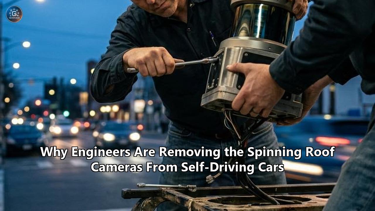
The iconic image that defined autonomous vehicle development for nearly two decades—a sleek prototype capped with a giant, mechanical spinning cylinder on its roof—has officially reached its end of life.
With Waymo initiating fully autonomous commercial operations for its sixth-generation Driver architecture across major U.S. metropolitan areas, and consumer automakers deploying Level 3 conditional autonomy in mass-production vehicles, autonomous driving engineers have systematically dismantled the rooftop "turret". In its place sits a new design philosophy: sleek, flush-mounted sensor arrays, in-cabin windshield optical modules, high-resolution solid-state light detection and ranging (LiDAR) units, and 4D imaging radar integrated directly into body panels and rooflines.
This hardware transition is not merely a cosmetic facelift. The removal of the spinning mechanical roof bucket represents a fundamental shift in how robotics engineers solve perception, aerodynamics, thermal management, and manufacturing economics.
The industry has moved past the era of academic research vehicles—where capturing a raw 360-degree point cloud from a single high vantage point trumped all real-world automotive constraints—into an era where cost-efficiency, weather resilience, passive cooling, and consumer styling dictate the hardware stack.
Examining the competing architectural responses to this shift reveals the distinct tradeoffs, technologies, and engineering philosophies shaping the next decade of autonomous mobility.
                     TRADITIONAL VS. MODERN AV SENSOR ARCHITECTURE

  [Old Paradigm: Spinning Roof Bucket]         [New Paradigm: Integrated Solid-State Fusion]

            +-----------------+                            +-----------------+
            |  Rotating Bucket|                            | Low-Profile Pod |
            |  (360° Mechanical|                            | (Camera/Radar)  |
            +--------+--------+                            +--------+--------+
                     |                                              |
             /---------------+-----\                        /---------------+-----\
            /                       \                      /   Behind Glass  \
           /       VEHICLE           \                    /    Solid-State    \
          |                           |                  |       LiDAR        |
          |  High Drag (Cd +0.04)     |                  |                    |
          |  High Cost ($75,000+)     |                  |  Sleek (Cd +0.00)  |
          |  Mechanical Failure Risk  |                  |  Sub-$500 Cost     |
          |                           |                  |  Solid-State Reliability
The Mechanical Legacy: Why the Spinning Dome Was King
To understand why autonomous vehicle engineers fought so hard to replace the mechanical spinning roof drum, one must first appreciate why it was universally adopted in the early days of autonomous driving research.
During the early DARPA Grand Challenges and the founding of Google’s Self-Driving Car Project, the primary constraint on autonomous driving was not vehicle design or power draw—it was getting sufficient 3D spatial data into primitive perception algorithms. The solution was mechanical LiDAR.
A traditional mechanical LiDAR operates by stacking laser emitters and photodetectors vertically inside a cylindrical casing. A high-precision electric motor rotates the entire optical array at 10 to 20 revolutions per second, sweeping laser beams across a full 360-degree horizontal field of view.
The Unmatched Advantages of the Central Roof Mounting
For over a decade, mounting a single 360-degree mechanical spinner at the absolute highest point of the vehicle was the most mathematically elegant approach to robotic perception:
- Unobstructed 360-Degree Line of Sight: A single elevated sensor could see over the vehicle’s bonnet, trunk, and adjacent low-lying obstacles, providing a uniform bird’s-eye view of the environment without blind spots caused by the vehicle’s own bodywork.
- Simplified Spatial Calibration: Because a single central sensor captured the surrounding environment, software engineers did not need to perform complex temporal or spatial calibration across dozens of disparate sensor streams. The origin point $(0,0,0)$ of the vehicle's spatial coordinate system was anchored directly to the center of the spinning roof cylinder.
- High Peak Laser Power Within Eye-Safety Limits: Eye-safety regulations strictly limit the amount of continuous laser energy that can be directed into a human eye. Because a mechanical system sweeps its laser beam rapidly across the horizon, energy is never concentrated in a single direction for more than a fraction of a millisecond. This allowed engineers to pump higher pulse energy into the lasers, achieving range detection exceeding 200 meters even with basic 905-nanometer silicon photodetectors.
The Fatal Flaws that Forced its Demise
Despite these optical advantages, the spinning roof bucket carried structural drawbacks that made mass commercial production impossible.
                     MECHANICAL VS. SOLID-STATE TRADEOFFS

+------------------------+---------------------------------+---------------------------------+
| Metric                 | Mechanical Spinning Roof Bucket | Flush Solid-State / MEMS        |
+------------------------+---------------------------------+---------------------------------+
| Moving Parts           | High (Bearings, Belts, Motors)  | Zero to Micro-mirrors           |
| Mean Time Between Fail | 1,000 - 5,000 Hours             | 50,000+ Hours (Automotive Grade)|
| Aerodynamic Drag (Cd)  | Adds +0.03 to +0.06             | Negligible (+0.00 to +0.005)    |
| Unit Cost (USD)        | $10,000 - $75,000               | $200 - $1,000                   |
| Power Consumption      | 40W - 100W                      | 5W - 15W                        |
| Environmental Hazard   | Ice/Mud jams spinning housing   | Sealed behind heated automotive glass|
+------------------------+---------------------------------+---------------------------------+
Mechanical Degradation and Vibration Sensitivity
Vehicles operate in brutal physical environments. They bounce over potholes, endure sustained chassis vibrations, sit in direct sunlight reaching internal temperatures over 80°C, and drive through sub-zero blizzards.
A mechanical spinning dome relies on precision ball bearings, optical slip rings (to transfer data and power across the rotating interface), and brushless motors.
Over tens of thousands of miles, mechanical wear leads to bearing play, micro-misalignments in optics, and electrical contact degradation in slip rings. The mean time between failures (MTBF) for early 360-degree spinning LiDARs ranged between 2,000 and 5,000 operating hours—unacceptable for commercial passenger cars designed to last 150,000+ miles over a 15-year operational lifespan.
Aerodynamic Drag and Battery Range Penalties
In the era of internal combustion engine prototypes, an aerodynamic drag penalty was simply a matter of slightly higher fuel consumption. But as the autonomous vehicle industry transitioned entirely to battery electric vehicle (BEV) platforms—such as Waymo's adoption of the Jaguar I-PACE and Zeekr platforms, and Cruise's deployment of custom electric pods—aerodynamics became a primary engineering constraint.
A large, cylindrical object mounted on a vehicle roof acts as a bluff body, creating significant pressure drag and turbulent wake. Wind-tunnel testing revealed that early prototype roof buckets increased a vehicle’s drag coefficient ($C_d$) by 0.03 to 0.06.
At highway speeds (70 mph), aerodynamic drag accounts for over 60% of total vehicle energy consumption. A 0.04 increase in $C_d$ translates to a 10% to 15% reduction in total electric driving range. For a robotaxi fleet operator, a 15% range penalty directly reduces daily operational revenue by forcing vehicles back to charging depots during peak hours.
Environmental Contamination and Cleaning Failures
A central spinning drum presents an enormous surface area exposed to road spray, rain, insect impacts, and snow accumulation. Because the outer casing spins or contains a rotating optic behind a clear stationary cylinder, applying mechanical wipers is exceptionally difficult.
Early clearing systems relied on high-pressure compressed air nozzles fired at the glass casing. However, under heavy freezing rain or sticky highway mud, air jets proved insufficient.
If mud caked onto a 60-degree sector of the spinning cylinder, the entire 360-degree point cloud suffered a localized black-out every single rotation, rendering the perception system partially blind multiple times per second.
Competing Paradigms: How the Industry Replaced the Spinning Bucket
As engineers abandoned the central mechanical spinner, the autonomous vehicle industry split into competing design philosophies. Rather than settling on a single universal hardware layout, major autonomous driving programs developed fundamentally different approaches to structuring their self-driving car sensors.
                   THREE COMPETING SENSOR PARADIGMS

  [PARADIGM 1: Distributed Multimodal]   [PARADIGM 2: In-Cabin Windshield]   [PARADIGM 3: Vision-Only Pure Camera]
  (Waymo Gen 6, Zoox, Mobileye Drive)    (Volvo EX90, Mercedes, Hesai ET25)    (Tesla FSD V12/V13, Cybercab)

      +------------------------+             +------------------------+             +------------------------+
      | - Sleek perimeter pods |             | - Sensor behind glass  |             | - Zero LiDAR or Radar  |
      | - 4x Solid-state LiDAR |             | - 1x Long-range LiDAR  |             | - 8-10 Optical Cameras |
      | - 13x 17MP Cameras     |             | - Wiped clean by blade |             | - Pure End-to-End AI   |
      | - 6x Imaging Radars    |             | - Zero aero penalty    |             | - Low cost ($400)      |
      +------------------------+             +------------------------+             +------------------------+
Approach 1: Distributed Multimodal Sensor Suites (Waymo Gen 6, Zoox, Mobileye Drive)
The primary response from Level 4 robotaxi operators has been replacing a single central sensor with a matrix of smaller, highly integrated solid-state or semi-solid-state sensors distributed strategically around the vehicle's perimeter.
Waymo’s sixth-generation hardware suite serves as the benchmark for this philosophy. Instead of the towering roof bucket seen on earlier generations, the Gen 6 system utilizes a low-profile, integrated roof cap combined with perimeter sensor pods mounted at the four corners of the roofline and body pillars.
                 WAYMO GEN 6 DISTRIBUTED MULTIMODAL LAYOUT

                      [Front Center: Camera/Radar/LiDAR]
                                 |
      [Left Roof Pod] -----------+----------- [Right Roof Pod]
     (Solid-State LiDAR                       (Solid-State LiDAR
      + 17MP Cameras)                          + 17MP Cameras)
                                 |
     [Left Pillar Camera] -------+------- [Right Pillar Camera]
                                 |
                      [Rear Integrated Tail Module]
Key Technical Components
- 13 High-Resolution Cameras: Waymo transitioned to custom 17-megapixel imagers capable of capturing high dynamic range (HDR) scenes with high thermal stability, enabling long-range object identification while reducing total camera count from previous generations.
- 4 Solid-State LiDAR Units: Replacing the heavy central mechanical spinner, four compact LiDAR modules are placed on the roof perimeter, overlapping their fields of view to provide an uninterrupted 360-degree 3D map extending beyond 500 meters.
- 6 Imaging Radar Units: 4D high-definition radars capable of measuring elevation, azimuth, and Doppler velocity simultaneously, bridging the gap between cameras and LiDAR in heavy rain, fog, and blowing snow.
- External Audio Receivers (EARs): Microphone arrays designed to localize emergency vehicle sirens and traffic audio directions.
The Engineering Tradeoffs
This distributed approach maintains high safety redundancy. If one sensor fails or is obstructed by debris, adjacent sensors with overlapping fields of view instantly fill the spatial gap. Furthermore, because the sensors are broken down into smaller modules, they are far easier to flush-mount into custom bodywork, dramatically improving aerodynamic efficiency and vehicle styling compared to early prototypes.
However, the distributed model requires precise spatial-temporal calibration. Because 23 individual sensor streams (cameras, LiDARs, and radars) originate from distinct physical coordinates across the vehicle body, the perception compute engine must constantly transform all incoming data into a single unified coordinate space. This places higher computational demands on onboard AI processors.
Approach 2: In-Cabin Behind-the-Windshield Integration (Luminar Iris, Hesai ET25, Volvo EX90)
A second major paradigm shift—favored by consumer automotive OEMs like Volvo, Mercedes-Benz, Polestar, and Lotus—places the primary long-range LiDAR inside the passenger compartment, directly behind the top edge of the front windshield.
Developments such as Hesai’s ET25 and Luminar’s Iris system reflect this approach, shrinking the vertical profile of solid-state LiDAR units down to 25 millimeters (about one inch), allowing them to fit between the headliner and the inner windshield glass.
                 IN-CABIN WINDSHIELD SENSOR INTEGRATION

             Roof Structure
    +----------------------------------+
    |  [Ultra-Thin Solid-State LiDAR]  |  <-- Cabin Interior (25mm height)
    +----------------------------------+
    ====================================  <-- Keep-Out-Zone (KOZ) Glass
             Windshield Glass               (AR Coated, High IR Transmittance)

     Outside Environment
The Engineering Advantages
- Total Protection from Environmental Hazards: By keeping the delicate optical system inside the climate-controlled cabin, the sensor is completely isolated from rain, snow, road grit, car washes, and direct physical damage.
- Built-in Wiping and Heating Infrastructure: Rather than engineering complex air-jet blowers or miniature motorized wipers for exterior pods, in-cabin sensors leverage the vehicle’s stock windshield wipers and defrosting wire grids. When snow or mud hits the sensor's view, the driver's normal wiper blade clears it instantly.
- Zero Aerodynamic Penalty: With no exterior protrusions, the drag coefficient ($C_d$) penalty is zero, preserving EV range and allowing sleek vehicle silhouettes.
The Physics Challenges: Glass Attenuation and Heat Dissipation
Mounting a laser sensor behind windshield glass introduces severe optical challenges. Standard automotive laminated glass is designed to block infrared radiation (IR) to prevent cabin overheating from sunlight. However, most automotive LiDARs operate at near-infrared wavelengths (905nm or 1550nm). Passing through a standard windshield can attenuate (weaken) the laser signal by up to 80% to 90%, severely degrading detection range.
To solve this, automakers and glass suppliers (such as Fuyao Glass) developed specialized "Keep-Out-Zone" (KOZ) windshields. These windshields feature localized optical windows coated with Anti-Reflective (AR) materials that permit over 98% transmittance of specific infrared laser frequencies while maintaining solar heat reflection across the rest of the glass.
                OPTICAL SIGNAL PASS-THROUGH COMPARISON

  Standard Automotive IRR Glass:
  Laser Pulse (100% Power) ===> [ Glass ] ===> Transmitted Signal (10%-20% Power) [FAILED]

  Specialized Keep-Out-Zone (KOZ) Glass:
  Laser Pulse (100% Power) ===> [ AR Window ] ===> Transmitted Signal (98% Power)  [SUCCESS]
A secondary challenge is thermal dissipation. Cabin rooflines trap high heat under direct sunlight, reaching temperatures up to 85°C. Solid-state LiDAR lasers and processing chips generate internal heat during operation. Dissipating that thermal load inside a sealed cabin without adding loud cooling fans near the driver's head requires sophisticated conductive thermal paths routed into the vehicle structure.
Approach 3: Vision-Only Pure Camera Architectures (Tesla FSD V12/V13, Cybercab)
Standing in stark contrast to multimodal fusion approaches is the vision-only philosophy pioneered by Tesla. Tesla eliminated mechanical spinning LiDAR years ago and subsequently removed front radars and ultrasonic sensors, relying exclusively on optical cameras fed directly into deep neural networks.
                     TESLA VISION-ONLY HARDWARE STACK

              [Triple-Camera Module (Windshield)]
                              |
    [B-Pillar Left] ----------+---------- [B-Pillar Right]
    [Fender Left] ------------+------------ [Fender Right]
                              |
                     [Rear License Plate Camera]
Key Technical Components
- 8 to 10 Surround Cameras: Positioned around the pillar glass, front windshield, front fenders, and rear license plate region.
- Pure End-to-End Neural Networks: Instead of explicit rangefinder sensors measuring distances to points in space, Tesla’s software stack uses spatial-temporal Neural Networks (Transformers and Occupancy Networks) to infer depth, velocity, and 3D structure directly from two-dimensional pixel arrays.
The Tradeoffs: Radical Cost Reductions vs. Physics Limits
The primary driver of the vision-only strategy is manufacturing scale and hardware cost economics.
A full multimodal sensor suite featuring high-performance solid-state LiDARs, 4D imaging radars, and redundant compute modules can add $2,000 to $8,000 to the bill-of-materials (BOM) cost of a vehicle. A vision-only suite costs roughly $300 to $500 total.
Furthermore, cameras do not require specialized exterior body modifications or optical cutouts; they sit flush behind standard glass panels.
However, the vision-only strategy relies on a single optical modality. When visual clarity drops significantly—such as in blinding glare, fog, heavy spray, or snowstorms—cameras lose raw pixel contrast.
While multimodal architectures fallback on active laser reflections (LiDAR) or radio-frequency penetration (Radar) to verify the presence of objects in low visibility, a vision-only system must rely entirely on neural network prediction.
Under the Hood: Solid-State Hardware Mechanics
The technological catalyst that allowed engineers to abandon the mechanical spinning roof bucket was the maturation of non-mechanical laser steering technology. Rather than physical electric motors rotating heavy mirrors and optical assemblies, modern self-driving car sensors manipulate laser light electronically or via micro-scale solid-state actuators.
              EVOLUTION OF LASER SCANNING TECHNOLOGIES

   1. Mechanical Spinning     2. MEMS Mirror Scanning     3. True Solid-State (OPA/Flash)
      +--------------+           +--------------+            +--------------+
      | Motor-Driven |           | Silicon Micro|            | Electronic   |
      | Rotating     |   ===>    | Vibrating    |   ===>     | Phase Shift  |
      | Optical Cylinder         | Mirror (1D/2D|            | (No Moving   |
      +--------------+           +--------------+            |  Parts)      |
                                                             +--------------+
1. MEMS (Micro-Electro-Mechanical Systems) LiDAR
Micro-Electro-Mechanical Systems (MEMS) represent the bridging step between pure mechanical systems and true solid-state electronics.
Instead of spinning an entire 2-pound optical housing, a MEMS LiDAR directs a stationary laser beam onto a tiny silicon mirror measuring just a few millimeters in diameter. This micro-mirror is mounted on electrostatic or piezoelectric flexures that vibrate at high frequencies along one or two axes, reflecting the laser beam across a predefined field of view.
- Advantages: Micro-mirrors have negligible mass, allowing scan rates exceeding 100 Hz with minimal power consumption. The size of the enclosure drops from the volume of a coffee tin down to the size of a deck of cards.
- Limitations: Because the physical micro-mirror mirror area is extremely small, capturing weak laser reflections returned from distant dark objects (e.g., a black car 200 meters away with 10% reflectivity) is optically challenging. Additionally, while microscopic, MEMS mirrors are still mechanical structures susceptible to severe resonance shocks if hit hard enough.
2. Optical Phased Arrays (OPA)
Optical Phased Arrays (OPA) apply the exact same physical principles used in advanced military radar systems to light waves. An OPA chip consists of an array of micro-scale optical phase shifters integrated onto a silicon photonics circuit.
By dynamically adjusting the phase delay of light emitted across adjacent channels on the chip, engineers create constructive and destructive wave interference patterns. This effectively steers the emitted laser beam in any direction across a 2D plane without a single moving part—microscopic or otherwise.
                        OPTICAL PHASED ARRAY SCANNING

   Laser Light Source
          |
   [Splitter Array] ===> [Phase Shifter 1] (+0° Delay)   \
                    ===> [Phase Shifter 2] (+45° Delay)  ===> Wavefront Directed Upwards
===> [Phase Shifter 3] (+90° Delay) /- Advantages: Unmatched physical reliability. With zero mechanical flexures or motors, an OPA sensor can withstand extreme automotive shock and vibration profiles indefinitely. Silicon photonics manufacturing allows OPA chips to be produced using standard semiconductor fabrication facilities, pushing unit costs down toward sub-$100 price points at massive volumes.
- Limitations: Controlling phase accuracy across thousands of light emitters on a single chip under varying operating temperatures remains technically complex. Thermal expansion can distort the phase delays, requiring active optical calibration circuits on the silicon die.
3. Flash LiDAR and SPAD Detector Arrays
Flash LiDAR operates similarly to a digital camera equipped with an invisible laser flash. Instead of sweeping a focused point laser across the horizon point by point, a Flash LiDAR emits a single, broad beam of laser light to illuminate an entire wide-angle scene instantaneously.
The reflected light is captured on a 2D matrix array of single-photon avalanche diodes (SPADs) or Time-of-Flight (ToF) pixels. Each individual pixel measures the precise time elapsed between the laser flash and the arrival of returning photons, constructing a complete 3D depth frame simultaneously.
                             FLASH LIDAR OPERATION

  +--------------------+  Pulsed Flash Light  +--------------------+
  | Flash Laser Transmitter |  ===============>  |  Target Scene      |
  +--------------------+                      |  (Pedestrian, Car) |
                                              +--------------------+
  +--------------------+  Reflected Photon    |
  | 2D SPAD Sensor Array|  <===============   |
  | (Measures ToF per  |                      |
  |  pixel instantly)  |                      |
+--------------------+ +--------------------+- Advantages: Flash LiDAR achieves extremely high frame rates (up to 60–100 frames per second) with zero motion distortion or spatial skewing caused by moving parts. This makes Flash LiDAR an ideal choice for short-range blind-spot monitoring around vehicle bumpers and door sills.
- Limitations: Distributing laser energy over a broad field of view simultaneously—rather than concentrating it into a tight continuous laser beam—drastically reduces maximum detection range under strict eye-safety energy limits. Consequently, Flash LiDARs are currently used primarily for short-range perception (0 to 50 meters) rather than long-range highway lookaheads.
Thermal, Aerodynamic, and Active Cleaning Dynamics
Eliminating the spinning roof bucket solved structural aerodynamic issues, but it introduced distinct thermal and cleaning challenges that required clever engineering solutions.
                     AERODYNAMIC DRAG FORCE VS. SPEED

   Drag Force (N)
     ^
  300|                                   / (Traditional Roof Bucket)
     |                                  /  Cd = 0.32
  200|                                 /
     |                                /  _ (Modern Integrated Suite)
  100|                               /_/   Cd = 0.27
     |                           _ -
    0+--------------------------+-------------------->
     0                         40                    70  Speed (MPH)
Drag Coefficients and Electric Range Preservation
Aerodynamic drag force is governed by the classic drag equation:
$$F_d = \frac{1}{2} \rho v^2 C_d A$$
Where:
- $\rho$ is air density
- $v$ is vehicle velocity
- $C_d$ is the drag coefficient
- $A$ is frontal surface area
A traditional spinning roof bucket increased both the frontal area ($A$) and the drag coefficient ($C_d$) simultaneously. The sharp geometric angles of the rotating cylinder caused airflow separation at the top trailing edge, creating a low-pressure turbulent vortex behind the vehicle.
Modern integrated sensor pods (like those on Waymo’s Gen 6 platform or Volvo’s EX90) are sculpted using computational fluid dynamics (CFD). The sensor housings feature continuous teardrop curvature profiles that encourage attached laminar airflow, suppressing boundary-layer separation.
By reducing the added aerodynamic drag down to near-zero levels, AV platform developers reclaimed up to 12% of battery efficiency at highway speeds, directly translating to extended operational range for electric robotaxi fleets.
Thermal Dissipation: From Rotary Air Cooling to Passive Heat Pipes
A rotating mechanical LiDAR benefited from an unintended side effect: as the optical cylinder spun rapidly in open air, it acted as a fan, shedding thermal heat generated by its laser drivers through forced convection.
When sensors are shrunk down and embedded into sealed bodywork, bumper grilles, or cabin windshields, forced air cooling is no longer available. Solid-state laser diodes (especially 905nm lasers) experience wavelength drift when junction temperatures rise. If a laser diode overheats, its emission wavelength shifts outside the narrow passband filter of the optical receiver, dropping perception sensitivity significantly.
To manage heat without loud exterior fans, modern integrated sensor pods use multi-stage thermal management strategies:
- Heat Pipe Arrays: Liquid vapor-chamber heat pipes draw thermal energy away from the laser substrate directly into aluminum or magnesium chassis structural beams.
- Phase-Change Materials (PCMs): Materials that absorb thermal energy during heavy compute spikes or hot ambient idling, melting slowly to buffer internal temperatures before solidifying when the vehicle is moving.
- Thermoelectric (Peltier) Coolers: Solid-state heat pumps mounted behind high-power silicon photonics dies to keep optical elements at precise target temperatures regardless of external weather.
Active Cleaning Systems: The Transition from Compressed Air to Integrated Fluids
Because a low-profile exterior sensor pod cannot be cleared by standard wipers, engineers developed automated cleaning systems built into the sensor housings.
                    INTEGRATED SENSOR CLEARING MODULE

       [Hydrophobic Anti-Smudge Coating]
                       |
       [Embedded Transparent Heaters (ITO Film)]
                       |
       [High-Pressure Fluid Micro-Nozzles]
                       |
       [Pulsed Ultrasonic Surface Transducer]
Modern integrated perimeter sensors use a four-tier cleaning process:
- Indium Tin Oxide (ITO) Heating Films: Microscopic, transparent conductive heating lines embedded into the protective sensor lens rapidly melt ice, frost, and snow buildup.
- Hydrophobic and Oleophobic Coatings: Surface chemical treatments cause rain droplets and mud spray to bead up and roll off instantly rather than forming light-distorting films.
- Micro-Fluidic Nozzles: High-pressure washer jets integrated directly around the outer frame of the sensor lens blast targeted squirts of cleaning fluid to break up dried mud or crushed insects.
- Ultrasonic Surface Cleaning: High-frequency piezoelectric transducers vibrate the outer optical cover at 20 kHz to 40 kHz, atomizing surface water droplets and shaking off dust particles in milliseconds without moving mechanical arms.
The Economics of Sensing: From $100,000 Buckets to $200 Chips
The removal of the spinning roof camera/LiDAR drum is equally driven by manufacturing economics. Early autonomous vehicle development was limited by hardware costs that made consumer adoption impossible.
            AVERAGE COST PER AUTOMOTIVE LIDAR MODULE (2012-2026)

   USD ($)
   $100,000 +-------------------\  (2012: Mechanical Spinning 64-Beam)
            |                    \
    $50,000 |                     \
            |                      \
    $10,000 |                       \=======\ (2020: Semi-Solid Mechanical)
            |                                \
       $500 +---------------------------------\-----> (2026: Solid-State / MEMS)
            0-----------------------------------------
           2012                 2020       2026
The Cost Collapse of Automotive LiDAR
In 2012, a high-performance 64-beam mechanical spinning LiDAR (such as the industry-standard Velodyne HDL-64E) carried a retail price exceeding $75,000 to $100,000 per individual unit. Because the sensor required hand-assembly of discrete optoelectronic elements, manual alignment of 64 individual laser-detector pairs, and complex mechanical assemblies, scaling production was labor-intensive and costly.
The shift toward solid-state and semiconductor-based designs completely inverted this cost structure:
- 2018–2020: Semi-solid-state MEMS and rotating mirror LiDARs reduced prices down to $5,000–$10,000 per unit.
- 2024–2026: Chinese LiDAR manufacturers (such as Hesai, RoboSense, and Seyond) alongside Western developers achieved mass-production scale. High-density MEMS and solid-state LiDARs crossed the threshold of $200 to $500 per unit for high-volume automotive production runs.
Supply Chain Scale in Consumer EVs
This price reduction was driven heavily by mass deployment across Chinese electric vehicle brands. Automakers such as Li Auto, NIO, XPeng, BYD, and Zeekr began standardizing solid-state LiDARs across consumer passenger vehicles priced as low as $25,000.
In 2024 alone, automotive LiDAR shipments exceeded 1.5 million units globally—a 240%+ year-over-year increase. By leveraging standard silicon semiconductor manufacturing processes (CMOS fabrication), optical sensor components scale along cost curves similar to microprocessors.
                     TOTAL HARDWARE SUITE COST COMPARISON

  [Early Prototype Fleet (2018)]         [Modern Gen-6 Robotaxi (2026)]
  - 1x Mechanical Spinner: $75,000       - 4x Solid-State LiDARs: $1,600
  - 4x Short-Range Radars: $2,000        - 13x 17MP Cameras:       $650
  - 6x Basic Cameras:       $1,200       - 6x 4D Imaging Radars:   $900
  - Custom Roof Mounts:     $5,000       - Integrated Pods:        $400
  --------------------------------       ------------------------------
  TOTAL BOM COST:         ~$83,200       TOTAL BOM COST:        ~$3,550
This drastic reduction in hardware cost transformed self-driving car sensors from high-cost experimental hardware into commercially scalable components. A robotaxi fleet operator can now equip a complete Level 4 redundant sensor stack—comprising multiple high-resolution cameras, solid-state LiDARs, and 4D imaging radars—for a fraction of the cost of a single historic mechanical spinning drum.
AI and Computational Advances: Software Compensating for Hardware
The physical removal of the central 360-degree spinning camera/LiDAR turret was only possible because AI perception software evolved beyond processing raw individual sensor streams.
                    PERCEPTION ARCHITECTURE EVOLUTION

  EARLY ARCHITECTURE (Bounding Box Detection):
  Mechanical Point Cloud ===> Hand-Crafted Heuristics ===> 3D Bounding Boxes
  Camera Images          ===> 2D Object Detection     ===> Late Heuristic Fusion

  MODERN ARCHITECTURE (BEV & Occupancy Transformers):
  13x Camera Feeds  \
  4x LiDAR Point Clouds ===> Multi-Modal Transformer ===> Unified 3D Occupancy Grid
  6x Radar Doppler Streams /  (e.g., SW-Former, BEV)     + Direct Velocity Vectors
The Shift from Hand-Crafted Late Fusion to BEV Transformers
In early autonomous driving architectures, perception software used "late fusion". The central 360-degree mechanical LiDAR generated a raw point cloud. Software algorithms independently drew 3D bounding boxes around clusters of points to identify cars, pedestrians, or cyclists.
Meanwhile, cameras independently classified objects in 2D space. A fusion algorithm then attempted to reconcile conflicts between the separate detections.
Modern autonomous systems rely on multi-modal Bird's-Eye-View (BEV) Transformer models and 3D Occupancy Networks. Algorithms such as Waymo’s SW-Former or deep Transformer architectures take raw, unrectified camera pixels, solid-state LiDAR point clusters, and 4D radar Doppler returns, projecting them simultaneously into a unified spatial-temporal latent space.
How Software Eliminates Physical Blind Spots
A single 360-degree mechanical roof spinner provided continuous physical spatial coverage. When replacing it with multiple distinct solid-state sensors, small physical overlap gaps can occur between sensor fields of view near the bodywork.
                       3D OCCUPANCY GRID CONTINUITY

  Physical Blind Gap Between Sensor A & Sensor B
                       |
                       v
    [Sensor A] ----> [   ] <---- [Sensor B]
                       |
                       +---> Spatial-Temporal Transformer Memory
                             (Predicts continuity based on past frames)
Modern AI architectures overcome these hardware boundaries through spatial-temporal tracking:
- Temporal Memory Buffers: If a low-lying object (e.g., a small dog or curb) momentarily passes through a narrow blind gap between a roof pillar camera and a bumper LiDAR, the neural network's temporal memory retains the object's exact 3D position, velocity vector, and volumetric shape based on previous frames.
- Volumetric Occupancy Grids: Rather than requiring a dense laser point cloud to identify an object, 3D Occupancy Networks divide the space surrounding the vehicle into voxel grids (3D cubic pixels). The network calculates the probability of each voxel being occupied ($P_{\text{occ}}$) and its vector velocity, regardless of whether the spatial data originated from camera imagery, LiDAR returns, or radar signals.
This algorithmic evolution removed the requirement for a single physical sensor to maintain direct line of sight to every point around the vehicle continuously. As long as the combined multimodal matrix covers the operational environment, deep learning models reconstruct a complete 360-degree continuous map of the surroundings.
What Lies Ahead: The Next Generation of Vehicle Perception
The removal of the spinning roof bucket marks the end of the experimental prototype era for autonomous vehicles. As autonomous driving transitions into mass commercial fleet operations and consumer L3 vehicle deployments, sensor hardware will continue to evolve.
                 EMERGING TECHNOLOGIES TO WATCH

  +-----------------------+-----------------------+-----------------------+
  | FMCW LiDAR            | Headlight / Lightbar  | Smart Sensor-Glass    |
  | (Coherent Laser)      | Integration           | Materials             |
  +-----------------------+-----------------------+-----------------------+
  | Measures distance AND | Completely hides      | Electrochromic        |
  | instant velocity per  | solid-state LiDARs    | optical elements      |
  | photon via Doppler.   | inside vehicle lighting| built into bodywork  |
  +-----------------------+-----------------------+-----------------------+
1. Frequency Modulated Continuous Wave (FMCW) LiDAR
Current Time-of-Flight (ToF) solid-state LiDARs measure distance by timing laser pulse reflections. Emerging Frequency Modulated Continuous Wave (FMCW) LiDARs emit a continuous laser beam whose frequency is constantly modulated.
By measuring the phase and frequency shift of returning light, an FMCW sensor calculates distance and instantaneous Doppler velocity for every single point in the point cloud simultaneously.
This allows perception software to instantly determine whether a object is moving toward or away from the vehicle without waiting for multiple camera frames, while providing total immunity to solar glare or interference from other nearby vehicle LiDARs.
2. Seamless Headlight and Lightbar Integration
Rather than mounting exterior pods, Tier-1 automotive suppliers (such as Marelli, Valeo, and Koito) are integrating solid-state LiDARs, micro-radars, and infrared cameras directly inside the headlight and taillight assemblies.
Positioning sensors behind headlight covers leverages existing heat dissipation, headlight washing systems, and protective polycarbonate lenses, making the autonomous hardware stack completely invisible to the consumer.
3. Smart Material Enclosures and Electrochromic Glass
Future vehicle architectures will incorporate smart materials that dynamically alter optical transparency. Electrochromic outer panels can turn transparent when active sensing is required and become opaque body-colored panels when parked or disengaged.
Additionally, advancements in metamaterials will allow radar frequencies to pass through painted metal-look plastic fascia with zero signal loss, eliminating visible bumper radar cutouts.
The Sunset of the Spinning Drum
The disappearance of the spinning roof drum marks a major milestone in autonomous vehicle engineering. What was once an unavoidable engineering compromise—a bulky, expensive, highly vulnerable mechanical tower required to capture raw environmental data—has been rendered obsolete by solid-state physics, aerodynamic optimization, manufacturing scale, and spatial AI models.
The debate in autonomous driving hardware has evolved. The question is no longer where to mount the spinning central roof bucket, but how best to blend low-profile solid-state sensors, advanced glass materials, and vision-only camera systems into sleek, aerodynamic, mass-producible vehicles.
As fully autonomous robotaxis roll into more cities and Level 3 automation becomes standard across consumer vehicles, the spinning roof bucket will remain an artifact of early robotic development—a reminder of the era when software adapted to rigid hardware constraints, before hardware scaled to meet the realities of the road.
Reference Summary & Industry Key Metrics
- Waymo Gen 6 Hardware Suite: 13 Cameras (17MP), 4 Solid-State LiDARs, 6 Imaging Radars, External Audio Receivers (EARs).
- Tesla Vision Stack: 8–10 Cameras, 0 Radar, 0 LiDAR; End-to-End Neural Network processing.
- In-Cabin LiDAR Dimensions: Reduced to ~25mm height for behind-the-windshield installation (Hesai ET25, Luminar Iris).
- Aerodynamic Impact: Drag Coefficient ($C_d$) reduction from +0.04 (spinning bucket) down to ~0.00 (integrated pods/in-cabin), preserving ~12% EV range at highway speeds.
- LiDAR Unit Cost Curve: Fallen from ~$75,000+ (2012 mechanical 64-beam) to $200–$500 (2026 solid-state/MEMS mass production).
Reference:
- https://lidarnews.com/robotaxi-tech-leader-uses-lidar/
- https://waymo.com/blog/2026/02/ro-on-6th-gen-waymo-driver/
- https://www.reddit.com/r/SelfDrivingCars/comments/12lz94o/hesai_unveils_ultrathin_lidar_et25_that_can_be/
- https://raychunyin00.medium.com/lidar-a-fools-errand-in-self-driving-cars-335870ba8a76
- https://www.astuteanalytica.com/industry-report/automotive-lidar-market
- https://www.techdogs.com/td-articles/trending-stories/waymo-vs-tesla-comparing-the-best-autonomous-vehicle-technology
- https://www.thinkautonomous.ai/blog/tesla-vs-waymo-two-opposite-visions/
- https://globalgpssystems.com/lidar/explore-the-different-types-of-lidar-technology-from-mechanical-to-solid-state-lidar/
- https://www.slamtec.com/en/news/detailen/mechanical-vs-solid-state-lidar-advantages-and-disadvantages
- https://siliconangle.com/2024/08/19/waymo-debuts-sixth-generation-driver-autonomous-driving-system/
- https://waymo.com/blog/2024/08/meet-the-6th-generation-waymo-driver/
- https://www.wardsauto.com/news/archive-auto-waymo-6th-generation-driver-autonomous-driving-hardware-robotaxi-lidar-ai/725519/
- https://www.hesaitech.com/the-secret-of-in-cabin-lidar-how-ar-coated-windshield-complements-the-et25/
- https://straitsresearch.com/report/lidar-market
- https://research.contrary.com/report/tesla-waymo-and-the-great-sensor-debate
- https://www.ic-components.com/blog/Mechanical-vs-Solid-State-LiDAR-Differences,Applications,and-Selection-Factors.jsp
- https://www.hesaitech.com/things-you-need-to-know-about-lidar-solid-state-and-hybrid-solid-state-whats-the-difference/
- https://www.robosense.ai/en/news-show-1484
- https://www.thinkautonomous.ai/blog/solid-state-lidar/
- https://www.thinkautonomous.ai/blog/solid-state-lidar/
- https://www.marketsandmarkets.com/ResearchInsight/automotive-solid-state-lidar-companies.asp