
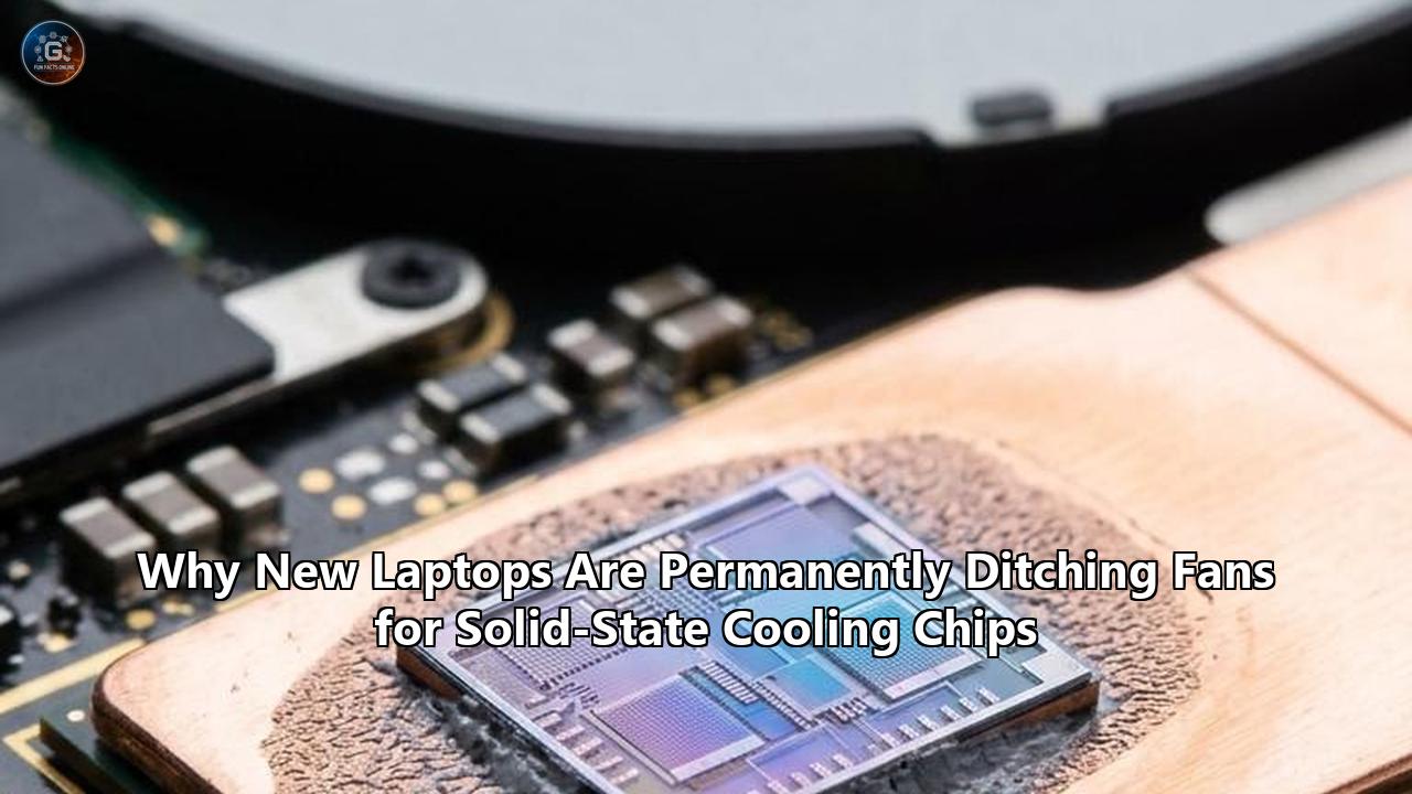
BERLIN — The mechanical cooling fan, a whirring staple of personal computing since the advent of portable x86 processors more than three decades ago, is facing an accelerated phase-out across the personal computer industry.
At the Lenovo Innovation World showcase in Berlin, Lenovo unveiled its AeroBlade architecture, an ultraportable production platform engineered in deep collaboration with San Jose thermal pioneer Frore Systems. The device completely omits conventional centrifugal blower fans. Instead, the notebook relies entirely on an array of active solid-state cooling chips to dissipate heat from its high-density system-on-chip (SoC). Lenovo's public demonstration comes alongside Intel's newly distributed Wildcat Lake reference platform, which similarly integrates sub-3-millimeter solid-state thermal modules into vapor-chamber assemblies to maintain a steady 15-watt thermal design power (TDP)—and burst up to 30 watts—in an enclosure measuring just 11.3 millimeters thick.
Simultaneously, semiconductor designer xMEMS Labs announced the mass-production tape-out of its XMC-2400 and XMC-4800 µCooling platforms, expanding monolithic silicon micro-pumps directly into enterprise and client M.2 solid-state storage. For decades, thermal dissipation was treated as an electromechanical aftermarket problem: silicon engineers fabricated processors, and mechanical engineers bent copper pipes, tacked on miniature radiators, and squeezed motorized impellers into plastic housings to suck air across the chassis.
That mechanical separation has reached an engineering dead end. As on-device artificial intelligence engines, neural processing units (NPUs), and dense multi-tile processor packaging demand sustained high-wattage throughput inside razor-thin enclosures, conventional rotary blowers can no longer generate the static pressure required to cool modern hardware without unacceptable acoustic penalties, severe thermal throttling, and mechanical failures.
The industry’s resolution is a quiet pivot to silicon-level thermodynamics. By swapping spinning plastic blades for vibrating piezoelectric membranes fabricated at wafer scale, solid state cooling chips generate record-breaking backpressures, dismantle insulating hydrodynamic boundary layers, and drop laptop acoustic footprints to the threshold of human hearing. The transition is transforming notebook industrial design from the motherboard out.
The Thermodynamics of Failure: Why Rotary Blowers Hit a Structural Wall
To understand why hardware manufacturers are aggressively abandoning rotary fans, one must look at the physical ceiling confronting electromechanical airflow inside ultra-thin mobile chassis.
For twenty years, laptop thermal engineering followed an iterative, predictable playbook:
- Place a sintered copper heat pipe or a sealed vapor chamber directly over the CPU and GPU.
- Evaporate and condense an internal working fluid (typically deionized water) to transfer heat laterally toward a fin stack positioned at the perimeter of the chassis.
- Spin a miniature centrifugal squirrel-cage fan to pull ambient air through underside intake vents and force it horizontally through the fin stack to exhaust the heat.
This architecture functioned adequately when laptops were 20 to 25 millimeters thick. However, the modern consumer and enterprise market demands notebooks between 10 and 13 millimeters thick. Within an 11-millimeter chassis, once the display glass, aluminum top plate, battery pouch, structural chassis ribs, keyboard deck, and printed circuit board (PCB) are accounted for, the total vertical z-height allocated to the cooling apparatus shrinks to roughly 3 to 4 millimeters.
Centrifugal fans suffer catastrophic performance degradation at these dimensions. A miniature rotary fan depends on vertical intake clearance: it must draw air downward through the eye of the impeller before turning that air 90 degrees and accelerating it outward between rotating blades. When the vertical gap between the fan impeller and the interior laptop wall drops below 1.5 millimeters, aerodynamic starvation occurs. Airflow cavitates, turbulence spikes, and volumetric throughput collapses.
Conventional Centrifugal Fan:
Ambient Air Intake (Requires Z-Height Clearance)
         │  │  │
         ▼  ▼  ▼
   ┌───────────────┐  <-- Motor Hub & Bearings (Subject to friction & wear)
   │  ┌───┐ ┌───┐  │
   │  │   │ │   │  │  <-- Rotating Blades (Generates low static pressure: 30-80 Pa)
   └──┴───┴─┴───┴──┘
         │
         ▼ (90-degree turn)
   ═════════════════► Airflow forced horizontally through heatsink fins
                      (Thick boundary layer insulates hot copper surfaces)

Solid-State Cooling Chip (Piezoelectric MEMS):
Ambient Air Drawn Silently from Chassis Cavity
         │  │  │
         ▼  ▼  ▼
   ┌───────────────┐  <-- Upper Membrane Layer (Vibrating at ultrasonic frequency)
   │  ▲▲▲▲▲▲▲▲▲▲▲  │  <-- Cavity Chamber (Acoustic resonance generates pressure)
   │  ▼▼▼▼▼▼▼▼▼▼▼  │  <-- Lower Membrane Layer
   └───────┬───────┘
           │
           ▼ Pulsating Micro-Jets (High static pressure: 1,750+ Pa)
   ═════════════════► Direct Jet Impingement
                      (Destroys hydrodynamic boundary layer down to 0.3mm fin gaps)
Worse, centrifugal fans produce minimal static backpressure. A top-tier, ultra-thin laptop fan spinning at a screeching 6,000 revolutions per minute rarely generates more than 50 to 80 Pascals of static pressure.
Static pressure is the mechanical muscle required to overcome airflow resistance. Because heat dissipation scales with surface area, engineers must pack copper heatsink fins as tightly as possible. Yet when fin gaps narrow below 0.8 millimeters, airflow resistance escalates exponentially. A low-pressure mechanical fan encounters these dense radiator fins like a solid brick wall. The air backs up, spills around the fan shroud, and recirculates inside the chassis. The laptop overheats, and the internal temperature monitor commands the processor to throttle down its clock speeds.
This dynamic created the persistent modern computing compromise known as the thermal throttling cliff. A modern 8-core or 16-core mobile SoC might advertise a burst clock of 5.1 GHz at a power envelope of 35 or 45 watts (the short-term Power Limit 2, or PL2). But because the miniature mechanical fan cannot evacuate the accumulated heat from the compact radiator, the system hits its 95°C or 100°C junction ceiling within 30 to 45 seconds. The BIOS immediately down-regulates the processor to its sustained power limit (PL1)—frequently falling to 15 watts, 12 watts, or even single digits. Consumers purchase silicon capable of desktop-class computation, only to operate the chip at a fraction of its potential under sustained workloads like video exporting, code compiling, or local machine-learning inferencing.
Beyond aerodynamics, mechanical blowers bring severe hardware vulnerabilities:
- Bearing degradation: Miniature fluid-dynamic and sleeve bearings dry out, gather dust, and suffer mechanical wear over 24 to 36 months, leading to rattling noises and catastrophic motor failure.
- Fin clogging: Low-pressure airflow cannot dislodge atmospheric detritus. Fine dust, lint, and pet hair weave into an impenetrable felt mat on the interior face of the heatsink fins, permanently degrading thermal conductivity until the machine is disassembled and cleaned.
- Acoustic irritation: Human hearing is acutely sensitive to the blade-pass frequency of miniature fans. When twenty tiny plastic blades spin past an exhaust port 100 times per second, they generate an acoustic tone precisely within the 1 kHz to 5 kHz bracket where human ear canals naturally amplify sound. The resulting high-pitched whine remains one of the most persistent user complaints in modern personal computing.
The Piezoelectric Breakthrough: How Solid-State Cooling Chips Operate
Solid state cooling chips solve this multi-variable physics failure by replacing bulk rotational movement with micro-electromechanical systems (MEMS) and piezoelectric actuation.
At the center of this transition are two front-running platforms: the AirJet series designed by Frore Systems, and the µCooling monolithic silicon architecture developed by xMEMS Labs. While their mechanical integration profiles differ, both leverage identical foundational physics: piezoelectric materials that flex with microscopic precision when stimulated by alternating electric fields, functioning as high-frequency acoustic air compressors.
+-----------------------------------+-----------------------------------+
| Metric / Feature                  | Conventional Mechanical Fan       |
+-----------------------------------+-----------------------------------+
| Typical Thickness (Z-Height)      | 4.5 mm to 9.0 mm                  |
| Static Backpressure Capability    | 30 to 80 Pascals                  |
| Primary Thermal Transfer Mode     | Bulk laminar/turbulent cross-flow |
| Acoustic Profile                  | 35 to 48 dBA (High-frequency tonal|
|                                   | whine at blade-pass frequency)    |
| Moving Parts / Mechanical Bearings| Rotary hub, copper sleeve/ball    |
|                                   | bearings, plastic impeller        |
| Ingress Vulnerability             | Dust accumulation; fin clogging;  |
|                                   | zero liquid resistance            |
| Assembly Method                   | Manual/robotic mechanical screw-in|
|                                   | with elastomer dampeners & tape   |
+-----------------------------------+-----------------------------------+
| Metric / Feature                  | Solid-State Cooling Chip (AirJet/ |
|                                   | µCooling)                         |
+-----------------------------------+-----------------------------------+
| Typical Thickness (Z-Height)      | 1.0 mm to 2.8 mm                  |
| Static Backpressure Capability    | 1,100 to 1,750+ Pascals           |
| Primary Thermal Transfer Mode     | High-velocity pulsating jet       |
|                                   | impingement                       |
| Acoustic Profile                  | 24 to 28 dBA (Broadband, inaudible|
|                                   | white noise below ambient room)   |
| Moving Parts / Mechanical Bearings| None; zero friction; solid-state  |
|                                   | oscillating silicon/piezo membrane|
| Ingress Vulnerability             | IP58 / IP68 dust-proof and        |
|                                   | water-resistant certified         |
| Assembly Method                   | Automated SMT pick-and-place, flex|
|                                   | PCB integration, direct bonding   |
+-----------------------------------+-----------------------------------+
Instead of rotating an axis to drag air behind an angled blade, an active solid-state cooling chip integrates an internal resonating cavity bounded by thin membranes coated with piezoelectric transducers—such as lead zirconate titanate (PZT) or doped aluminum nitride.
When an alternating voltage is applied to these membranes, they oscillate upward and downward at ultrasonic or near-ultrasonic frequencies. The downward motion expands the cavity, drawing air through microscopic intake apertures. As the voltage polarity reverses, the membranes flex inward at extreme acceleration, compressing the air within the chamber. The pressurized air is forced through micro-machined venturi nozzles, transforming static chamber pressure into focused, high-velocity micro-jets of air.
This continuous cycle occurs tens of thousands of times per second. Crucially, the air does not leave the chip as a gentle, broad cross-breeze. It exits as a high-frequency array of pulsating jets directed perpendicularly or near-perpendicularly against a heat-transfer surface—a process known in fluid dynamics as jet impingement.
Breaking the Hydrodynamic Boundary Layer
The thermal efficacy of solid state cooling chips stems directly from their ability to solve the boundary layer problem.
Whenever air flows over a solid stationary surface—such as the copper baseplate of a heatsink—fluid friction forces the air molecules immediately adjacent to the copper to come to a complete standstill. This is the "no-slip condition" of fluid mechanics. As a result, a stagnant cushion of stationary air forms directly over the heated metal: the hydrodynamic boundary layer.
THERMAL BOUNDARY LAYER IMPEDANCE:

Conventional Cross-Flow Air:
======================= Fluid Stream (Moving Air) =======================
  - - - - - - - - - - - Velocity Gradient Transition - - - - - - - - - -
-------------------------------------------------------------------------
████████████████████ Stagnant Boundary Layer (Thermal Insulator) █████████
-------------------------------------------------------------------------
▓▓▓▓▓▓▓▓▓▓▓▓▓▓▓▓▓▓▓▓ Heated Copper Heatspreader Surface ▓▓▓▓▓▓▓▓▓▓▓▓▓▓▓▓▓
                         HEAT TRAPPED AT SURFACE

Jet Impingement from Solid-State Micro-Jets:
               │ │ │   High-Velocity Pulsed Jets   │ │ │
               │ │ │    (Frequency: 20-40 kHz)     │ │ │
               ▼ ▼ ▼                               ▼ ▼ ▼
-------------------------------------------------------------------------
   \ \ \  Boundary Layer Completely Disrupted & Blown Away  / / /
-------------------------------------------------------------------------
▓▓▓▓▓▓▓▓▓▓▓▓▓▓▓▓▓▓▓▓ Heated Copper Heatspreader Surface ▓▓▓▓▓▓▓▓▓▓▓▓▓▓▓▓▓
                    DIRECT CONVECTIVE REMOVAL (3x h)
Air is an exceptionally poor conductor of heat; its thermal conductivity is approximately $0.026 \text{ W}/(\text{m}\cdot\text{K})$, compared to roughly $400 \text{ W}/(\text{m}\cdot\text{K})$ for pure copper. In a traditional laptop cooling assembly, the heat generated by the processor must conduct through this insulating blanket of stagnant air before the fan's moving cross-flow can sweep it away. The thicker the boundary layer, the higher the thermal resistance ($R_{\theta}$), and the hotter the CPU runs.
To express this quantitatively, the rate of convective heat transfer ($Q$) is governed by Newton's Law of Cooling:
$$Q = h \cdot A \cdot (T_s - T_\infty)$$
Where:
- $h$ is the convective heat transfer coefficient,
- $A$ is the active surface area,
- $T_s$ is the surface temperature of the heat sink, and
- $T_\infty$ is the ambient temperature of the approaching air.
In a conventional laptop fan system, where air flows parallel to the heatsink fins, the boundary layer grows thicker as the air travels along the length of the channel. The average heat transfer coefficient ($h$) in such laminar channel flows typically hovers between $50 \text{ and } 150 \text{ W}/(\text{m}^2\cdot\text{K})$.
Solid-state micro-jets alter this equation entirely. Because the micro-jets strike the heated copper substrate at high velocities (frequently exceeding 30 to 40 meters per second at the nozzle exit), they physically punch through the hydrodynamic boundary layer. The stagnation zone is destroyed. The high-frequency pulsation continually strips newly formed air cushions away from the metal.
Consequently, the localized heat transfer coefficient ($h$) beneath a pulsating micro-jet array leaps to values between $300 \text{ and } 600 \text{ W}/(\text{m}^2\cdot\text{K})$—a three- to fourfold improvement in heat transfer efficiency per unit of surface area.
The Pressure-Volume Transformation
The second critical physics advantage lies in static backpressure. While a conventional centrifugal laptop fan produces roughly 60 Pascals of pressure, an active solid-state module like the Frore Systems AirJet Mini G2 produces 1,750 Pascals—nearly thirty times greater backpressure.
Backpressure Comparison (Pascals):
┌───────────────────────────────┬────────┐
│ Conventional Laptop Fan       │ 60 Pa  │
├───────────────────────────────┼────────┤
│ xMEMS XMC-1200 Micro-Pump     │ 1100 Pa│
├───────────────────────────────┼────────┤
│ Frore Systems AirJet Mini G2  │ 1750 Pa│
└───────────────────────────────┴────────┘
This monumental increase in backpressure fundamentally alters heat sink design. Because the solid-state chip can push air against immense fluid resistance, thermal engineers are no longer forced to use wide, 1-millimeter gaps between heatsink fins to prevent airflow stalling. Instead, they can compress fin gaps down to 0.3 millimeters or even integrate micro-channel cold plates directly beneath the cooling chip.
This massively multiplies the total internal surface area ($A$) packed into a given footprint. By simultaneously doubling the convective heat transfer coefficient ($h$) via boundary layer destruction and tripling the available surface area ($A$) via ultra-dense fin geometries, solid state cooling chips dissipate identical or superior thermal wattages compared to massive mechanical blowers, while occupying a fraction of the physical volume.
Inside the Silicon: Frore Systems vs. xMEMS Labs
The commercialization of solid-state active cooling is driven by two distinct engineering methodologies, spearheaded respectively by Frore Systems and xMEMS Labs. While both share the objective of displacing mechanical rotary assemblies, their material compositions, packaging architectures, and market targets reflect divergent semiconductor philosophies.
Frore Systems AirJet Architecture:
┌────────────────────────────────────────────────────────┐
│ Top Cap & Particulate Filter (IP68 Membrane)           │
├────────────────────────────────────────────────────────┤
│ Piezoelectric Composite Actuators (Acoustic Resonance) │
├────────────────────────────────────────────────────────┤
│ Precision Air Cavity (1,750 Pa Backpressure Chamber)   │
├────────────────────────────────────────────────────────┤
│ Micro-Nozzle Ejector Array                             │
├────────────────────────────────────────────────────────┤
│ Integrated Copper Vapor Chamber / Heat Spreader Base   │
└────────────────────────────────────────────────────────┘
Result: Self-contained 2.8mm thermal engine designed to absorb
and eject up to 5-10W of heat per individual chip module.

xMEMS Labs µCooling Architecture:
┌────────────────────────────────────────────────────────┐
│ Monolithic Silicon Die (Single-wafer MEMS fabrication) │
├────────────────────────────────────────────────────────┤
│ PiezoMEMS Ultrasonic Transducer Layer (PZT on Silicon) │
├────────────────────────────────────────────────────────┤
│ Micro-Machined Fluidic Channels (<1.0mm Total Profile) │
├────────────────────────────────────────────────────────┤
│ SMT-Compatible Contact Pads for Pick-and-Place Reflow  │
└────────────────────────────────────────────────────────┘
Result: Ultra-miniaturized 1mm-thin silicon component treating
air movement as an integrated circuit, targetable at SSDs and SoCs.
Frore Systems: Composite Resonators and System-Level PAKs
Frore Systems, established by Dr. Seshu Madhavapeddy and Surya Ganti in San Jose, entered the sector by developing modular, sub-system-ready thermal engines.
Frore’s core hardware, the AirJet Mini and the subsequent AirJet Mini G2, does not attempt to be a bare, raw silicon die. Instead, it is an integrated multi-material module measuring 27.5 mm × 41.5 mm, with a thickness of just 2.8 mm (reducing to 2.5 mm in slim revisions). Inside the module, high-reliability composite piezoelectric membranes oscillate out of phase.
Air enters through filtered vents on the top face of the device, enters the compression cavity, and is ejected downward through an array of micro-jets against an integrated copper baseplate. The baseplate absorbs heat from the laptop’s underlying vapor chamber or heat spreader, and the high-velocity jets sweep the heat horizontally through side exhaust channels at velocities approaching 20 meters per second.
Each individual AirJet Mini G2 chip can silently remove up to 5.25 watts of net thermal energy while consuming approximately 1 watt of operational electricity. Crucially, the modules are designed to scale linearly:
- Two modules (AirJet PAK 2C): Dissipates roughly 10.5 watts of heat, ideal for thin-and-light tablets and passive convertibles.
- Three modules (AirJet PAK 3C): Dissipates 15.75 watts of heat, fitting directly into ultraportable laptop platforms like Intel’s Wildcat Lake and the Lenovo AeroBlade.
- Five modules (AirJet PAK 5C): Removes up to 26 to 30 watts of sustained thermal energy in high-performance portable workstations and compact edge-AI compute engines.
Frore’s recent focus has centered on its AirJet PAK products. Recognizing that laptop OEMs cannot easily afford the engineering overhead of routing custom air ducts for individual cooling chips, Frore integrated multiple AirJet units into standardized, plug-and-play packages measuring 6.5 mm in thickness, complete with internal sensors and autonomous control circuitry.
This autonomous intelligence, dubbed "Thermoception," allows the cooling package to monitor its own thermal environment and dynamically modulate its membrane frequencies without requiring instructions from the host system’s central processing unit or BIOS firmware.
xMEMS Labs: Monolithic Silicon µCooling
While Frore Systems builds micro-electromechanical thermal sub-assemblies, xMEMS Labs approaches the problem from pure semiconductor manufacturing.
Capitalizing on its foundational work in solid-state MEMS audio speakers, Santa Clara-based xMEMS adapted its piezoMEMS manufacturing pipeline to produce the world’s first monolithic all-silicon active micro-cooling fans: the XMC-2400 and the miniaturized XMC-1200.
The XMC-2400 measures an astonishingly thin 9.3 mm × 7.6 mm × 1.08 mm, weighing less than 150 milligrams. It is fabricated on standard silicon wafers using advanced photolithography and reactive-ion etching, placing microscopic vibrating silicon membranes directly onto a silicon substrate.
The technical distinction is profound:
- SMT Reflow Compatibility: Unlike any mechanical fan ever manufactured, the xMEMS chip can withstand the extreme 260°C thermal profiles of standard surface-mount technology (SMT) reflow ovens. This means hardware manufacturers do not need human assemblers or specialized mechanical arms to screw the fan into a chassis. The cooling chip is placed directly onto the motherboard PCB by high-speed pick-and-place robotics alongside DRAM chips, capacitors, and microcontrollers.
- True Solid-State Architecture: There are no discrete mechanical fasteners, hinges, or multi-material assemblies. The membrane, cavity walls, and nozzles are etched from single-crystal silicon. Silicon exhibits zero mechanical fatigue when operated within its design limits; it does not stretch, deform, or wear down over billions of cycles, yielding an operating lifespan exceeding 100,000 hours.
- Hyper-Localized Placement: Because the XMC-2400 has a z-height of barely 1 millimeter, it can be mounted directly on top of individual, localized thermal hotspots where a fan could never fit—such as directly on an NVMe controller die, tucked beneath an electromagnetic interference (EMI) shield, or inside the hinge cavity of an ultra-thin foldable laptop.
With an active power consumption of only 30 to 150 milliwatts, the xMEMS architecture focuses on component-level thermal mitigation, exhausting up to 1,100 Pascals of backpressure to force cooling air across tiny localized regions.
Eliminating the Acoustic Spike: Psychoacoustics and Ultrasonic Frequencies
The shift to solid state cooling chips is as much an acoustic evolution as a thermal one.
To understand why a laptop cooled by solid-state chips sounds radically different from a fan-cooled machine, one must examine the science of psychoacoustics—the psychological and physiological responses to sound.
The human ear does not perceive sound pressure levels uniformly across all frequencies. In the early 20th century, researchers Harvey Fletcher and Wilden A. Munson mapped human auditory sensitivity across the acoustic spectrum, formulating what are now standardized as the Equal-Loudness Contours (ISO 226).
EQUAL-LOUDNESS SENSITIVITY CURVE (A-Weighting Emphasis):
Acoustic
Sensitivity
  ▲
  │                       Peak Human Sensitivity
  │                           (1 kHz - 4 kHz)
  │                                 ╭─╮
  │                                ╭╯ │ ╰╮  <-- Mechanical Fan Whine
  │                               ╭╯  │  ╰╮     (Blade-pass harmonics)
  │                              ╭╯   │   ╰╮
  │                             ╭╯    │    ╰╮
  │                            ╭╯     │     ╰╮
  │                           ╭╯      │      ╰╮
  │      Low-Frequency       ╭╯       │       ╰─╮
  │      Motor Rumble       ╭╯        │         ╰╮
  │       (100 - 300 Hz)   ╭╯         │          ╰╮
  │        ╭───────────────╯          │           ╰────────────────
──┴────────┴──────────────────────────┴────────────────────────────►
  0 Hz   100 Hz                     2 kHz        16 kHz     20+ kHz
                                                            (Ultrasonic:
                                                             AirJet / µCooling)
The human auditory canal acts as an acoustic resonator with a fundamental resonance peak between 2,500 Hz and 4,000 Hz. Evolutionary biology tuned human ears to be hypersensitive in this spectrum, which corresponds directly to the critical frequencies of human speech, an infant's cry, or the crack of a predator's branch.
Unfortunately, the rotational mechanics of miniature laptop blowers place their primary acoustic emissions directly into this zone of maximum sensitivity.
A standard laptop fan possesses a specific number of blades ($B$), typically between 25 and 45 thin plastic fins. When the impeller rotates at an angular velocity ($N$) of 5,400 RPM (90 revolutions per second), it produces an acoustic artifact known as the Blade-Pass Frequency (BPF):
$$\text{BPF} = \frac{B \cdot N}{60}$$
For a 31-blade fan spinning at 5,400 RPM:
$$\text{BPF} = \frac{31 \cdot 5400}{60} = 2,790 \text{ Hz}$$
The fundamental acoustic signature of that fan is a pure tonal spike at 2,790 Hz—smack in the center of human hearing’s most sensitive resonance channel. Even if a sound meter registers the total sound pressure level of the laptop at a modest 36 decibels (dBA), the narrow-band tonal spike cuts through ambient background noise with piercing clarity. Users interpret this tone not as neutral air movement, but as an irritating, high-pitched mosquito-like whine.
Solid state cooling chips decouple acoustic emissions from human ear physiology via two distinct mechanisms:
1. Ultrasonic Actuation
The piezoelectric membranes inside chips like the xMEMS XMC-2400 oscillate at ultrasonic frequencies—typically exceeding 20 kHz, and often driving at 40 kHz or higher. The primary mechanical oscillation takes place entirely outside the hearing range of the human ear, which terminates at approximately 20 kHz in young children and drops toward 14 to 16 kHz in typical adults. Even if the internal membranes vibrate with considerable physical acceleration, they produce no audible acoustic fundamental tone.
2. Broadband White-Noise Decoupling
While the membranes themselves oscillate ultrasonically, the high-velocity air moving through the intake and exhaust ports does interact with air molecules, generating fluid turbulence. However, because this fluid motion originates from hundreds of microscopic, asynchronous micro-jets rather than a synchronized rotating blade passing an exhaust cowl, the resulting sound energy is distributed evenly across a flat, broadband spectrum.
Instead of a narrow, high-energy spike at 2,800 Hz, solid-state chips generate diffuse, low-level white noise that resembles the sound of a distant ocean breeze or gentle air conditioning. When measured in an anechoic chamber, a system utilizing three AirJet Mini modules running at maximum thermal capacity outputs an acoustic level between 24 and 28 dBA.
To put that figure in context:
- A typical modern open-plan office registers approximately 45 to 50 dBA.
- A quiet residential library registers roughly 35 to 40 dBA.
- A secluded bedroom at midnight registers roughly 30 dBA.
- The internal acoustic floor of typical audio testing equipment hovers near 25 dBA.
At 24 to 28 dBA, the sound produced by solid state cooling chips drops completely below the ambient ambient noise floor of virtually any real-world environment where a laptop is operated. Unless a user presses their ear directly against the exhaust vent in a dedicated acoustic chamber, the device is functionally, perceptually silent.
Redesigning the Motherboard: Direct-Die Integration and Component-Level PAKs
The eradication of rotary blowers is sparking a structural re-engineering of mobile personal computer architecture.
For thirty years, PC motherboard layouts were constrained by the physical presence of the fan housing. Because a centrifugal fan requires an expansive, empty cylinder cut straight through the interior of the laptop, motherboard designers were forced to route signal traces, power rails, and silicon placement around the cooling assembly. Motherboards were carved into asymmetrical "L" or "C" shapes, with complex high-speed interconnects lengthened to navigate around the fan cowl.
With solid-state active cooling, the cooling mechanism is no longer a separate, bulky mechanical fixture. It is treated as an integrated surface component.
CONVENTIONAL MOTHERBOARD ARCHITECTURE:
┌────────────────────────────────────────────────────────┐
│  ┌──────────────┐                  ┌────────────────┐  │
│  │ Rotary Fan   │◄─── Long ───►    │ Mini-Heatsink  │  │
│  │ Assembly     │     Copper       └────────────────┘  │
│  │ (35mm x 35mm)│   Heat Pipes              │          │
│  └──────────────┘                           ▼          │
│         ▲                            ┌──────────────┐  │
│         │ Forced Air                 │ CPU / GPU    │  │
│         │ Path                       │ Complex SoC  │  │
│  ┌──────┴───────┐                    └──────────────┘  │
│  │ Sinuous, "L"-│                           ▲          │
│  │ Shaped PCB   │                           │          │
│  │ (Long traces)│◄─────── Power Delivery ───┴───────┐  │
│  └──────────────┘         Circuits (VRMs)           │  │
└────────────────────────────────────────────────────────┘

SOLID-STATE DIRECT-STACK ARCHITECTURE:
┌────────────────────────────────────────────────────────┐
│  Compact, Rectangular High-Density PCB                 │
│                                                        │
│       ┌────────────────────────────────────────┐       │
│       │ Exhaust Port Venting Directly Outside  │       │
│       ├────────────────────────────────────────┤       │
│       │ Solid-State Cooling Chip Array         │       │
│       │ (Frore AirJet PAK / xMEMS µCooling)    │       │
│       ├────────────────────────────────────────┤       │
│       │ Micro-Vapor Chamber / Cold Plate       │       │
│       ├────────────────────────────────────────┤       │
│       │ Modern Heterogeneous Processor (SoC)   │       │
│       └────────────────────────────────────────┘       │
│                            ▲                           │
│                            │ Short Power Traces        │
│       ┌────────────────────┴───────────────────┐       │
│       │ Expanded Lithium-Polymer Battery Pouch │       │
│       │ (Reclaims 15-20% internal chassis vol) │       │
│       └────────────────────────────────────────┘       │
└────────────────────────────────────────────────────────┘
In the newly demonstrated Lenovo AeroBlade architecture, the entire mainboard has been consolidated into a compact, rectangular strip occupying the top 20% of the notebook's lower chassis. The sprawling, winding sintered copper heat pipes that characterized previous generations have been entirely eliminated.
In their place sits a direct-stack assembly:
- The Silicon Layer: The heterogeneous SoC (integrating CPU cores, GPU execution units, NPU tensor arrays, and on-package memory) sits soldered to the PCB.
- The Micro-Vapor Chamber: A paper-thin (0.4 mm) copper-clad vapor chamber spreads heat laterally across a compact, uniform plane directly above the silicon die.
- The Solid-State Array: An array of solid-state active cooling chips is bonded directly onto the vapor chamber using phase-change thermal interface materials (TIM).
- The Direct Exhaust Duct: Pressurized micro-jets draw air from microscopic acoustic slits beneath the keyboard deck, direct the pulsed air onto the vapor chamber surface, and eject the hot air directly out of rear exhaust louvers.
This direct-stack approach yields massive spatial dividends. In a typical 13-inch ultraportable laptop, the mechanical fan, motor housing, and radiator cowl occupy between 25 and 35 cubic centimeters of precious internal volume. An AirJet PAK array providing equivalent or superior heat rejection occupies less than 8 cubic centimeters.
Engineers are using this reclaimed internal volume to address the single most vital metric for mobile users: battery capacity.
By reclaiming the space previously consumed by empty fan chambers and sprawling copper conduits, system architects are expanding internal lithium-polymer battery cells by 15% to 22% by volume. In a chassis class that traditionally maxed out at a 54 watt-hour battery, manufacturers can now fit a 65 to 68 watt-hour pack. Paired with the elimination of the 2-to-3-watt parasitic power draw demanded by mechanical fan motors running at high RPMs, total device battery endurance during active mixed workloads extends by two to three hours.
Solving the Storage Chokepoint: PCIe Gen 5 SSD Thermal Dissipation
While central processing units have captured the bulk of thermal headlines, a quiet crisis has simultaneously gripped laptop high-speed storage. The adoption of solid-state active cooling is proving equally transformative for non-volatile storage.
The personal computer industry’s transition to the PCI Express 5.0 (PCIe Gen 5) bus standard increased theoretical sequential drive throughput to an extraordinary 14 gigabytes per second (GB/s). However, pushing data at 14 GB/s across four high-speed PCIe lanes demands immense electrical energy. Modern Gen 5 SSD controller chips, fabricated on dense process nodes, regularly pull between 9 and 14 watts of power under sustained read/write cycles.
All of that electrical energy is converted directly into heat over an area no larger than a postage stamp.
THE M.2 THERMAL THROTTLING CASCADE:
┌─────────────────────────────────────────────────────────────────┐
│ PCIe Gen 5 SSD Controller (Uncooled / Passively Cooled)         │
├─────────────────────────────────────────────────────────────────┤
│ Ambient Temperature: 25°C                                       │
│ 00:00 - High-Speed Sustained Transfer Commences (14.2 GB/s)     │
│ 00:15 - Controller Junction Temp hits 70°C                      │
│ 00:35 - Temp breaches Critical Threshold (82°C)                 │
│ 00:36 - Controller Firmware Executes Thermal Throttle Drop      │
│         Transfer Speed Collapses: 14.2 GB/s ──► 1.8 GB/s        │
└─────────────────────────────────────────────────────────────────┘
Result: 87% loss of storage throughput to prevent permanent flash damage.

WITH INTEGRATED SOLID-STATE µCOOLING (xMEMS XMC-2400):
┌─────────────────────────────────────────────────────────────────┐
│ PCIe Gen 5 SSD with In-Drive Solid-State Cooling Chip           │
├─────────────────────────────────────────────────────────────────┤
│ Active Heat Removal: ~3.0 Watts Direct Extraction               │
│ Controller Temperature Stabilized at: 61°C (Continuous)         │
│ Sustained Throughput: 13.8 GB/s Flatline (Indefinite Operation) │
└─────────────────────────────────────────────────────────────────┘
Result: Zero thermal throttling without adding bulky desktop-style heatsinks.
NAND flash memory and its associated controller ICs possess strict, unforgiving thermal operating boundaries:
- Controller ICs experience silicon timing errors and thermal breakdown when operating temperatures exceed 80°C to 85°C.
- NAND Flash Cells actually prefer warm conditions during write cycles to minimize crystal lattice strain, but suffer severe data retention degradation and leakage if sustained read/idle temperatures cross 70°C.
In an ultra-thin laptop, there is zero room to mount the massive aluminum fin stacks or copper pipe blocks that desktop motherboards use to keep Gen 5 drives functional. As a consequence, laptops equipped with Gen 5 drives have suffered from extreme thermal throttling.
When a user initiates a large file transfer, a game install, or a 4K/8K video render cache write, the drive achieves its advertised 14 GB/s speed for roughly 20 to 30 seconds. As the bare controller die rapidly spikes past 83°C, the drive’s internal throttle logic intervenes, instantly slashing PCIe lane throughput to prevent silicon destruction. Speeds plummet from 14,000 MB/s down to 2,000 MB/s or even 800 MB/s—slower than a last-generation PCIe Gen 3 drive.
Solid state cooling chips solve this storage chokepoint through hyper-localized active thermal extraction.
In May, xMEMS Labs detailed its dedicated µCooling platform designed specifically for standard M.2 2280 client SSDs and enterprise E3.S data center drives. Because an xMEMS XMC-2400 chip is barely 1.08 millimeters thick, drive manufacturers can mount the solid-state cooling chip directly onto the M.2 printed circuit board, sitting flush beside the controller silicon beneath a paper-thin copper thermal label.
Operating on just 150 milliwatts of power pulled from the drive’s 3.3V rail, the chip evacuates up to 3 watts of net heat directly from the controller package, reducing local component temperatures by 18% to 30%. This targeted heat rejection lowers thermal resistance by nearly 30%, preventing the controller from ever crossing its 80°C safety trigger. For the first time, ultra-thin mobile workstations can maintain unthrottled, continuous multi-gigabyte-per-second storage bandwidth without relying on chaotic ambient air currents from a distant CPU fan.
The Economics of Fab-Scale Cooling: Yields, Cost Curves, and SMT Assembly
If solid-state cooling chips possess such indisputable aerodynamic, physical, and acoustic advantages over mechanical fans, what kept them from dominating the hardware market sooner?
The answer lies in the harsh manufacturing economics of consumer hardware.
For three decades, the mechanical centrifugal blower fan held a virtually unbeatable economic advantage: it was remarkably cheap to produce. Stamped plastic impellers, mass-wound copper stators, and basic bronze sleeve bearings are commoditized goods produced in the tens of millions across Asian manufacturing hubs. A standard laptop blower costs an original design manufacturer (ODM) between $2.50 and $4.50 per unit.
In contrast, the first generations of solid state cooling chips faced the steep pricing curve common to all cutting-edge semiconductor innovations.
Early modules, produced in lower volumes with complex multi-material bonding steps, commanded prices between $15 and $20 per unit. Because a mid-range laptop might require two or three modules to achieve sufficient wattage dissipation, the thermal bill of materials (BOM) exploded from $4.00 to nearly $45.00—an unthinkable margin hit in an industry where PC OEMs routinely make product decisions based on cost differences of fifteen cents.
Between 2024 and 2026, three structural breakthroughs altered this cost equation:
1. Wafer-Scale Yield Optimization
Early MEMS manufacturing suffered from membrane fatigue and yield fallout during the deposition of the piezoelectric layers. Piezoelectric ceramic films like PZT require tight crystallographic orientation; any microscopic lattice void or micro-crack can cause a membrane to tear during high-frequency ultrasonic testing.
Over the past twenty-four months, foundries refined thin-film deposition techniques, migrating production to mature 200 mm (8-inch) and specialized 300 mm wafer lines. Yield rates for monolithic piezoMEMS devices have climbed past 90%, causing the bare-die manufacturing cost to collapse along standard semiconductor learning curves.
2. Elimination of Downstream Manufacturing Labor
When an ODM builds a laptop using traditional mechanical fans, the thermal sub-system incurs substantial manual and semi-automated assembly costs:
- Thermal paste must be robotically screened onto the dies.
- The copper heat pipe and radiator array must be positioned and hand-screwed into threaded chassis bosses using precise torque-limiting drivers to avoid cracking the silicon die.
- The discrete fan unit must be positioned, screwed into separate chassis standoffs, mechanically tethered via a delicate 4-pin wiring harness, and sealed to the radiator exhaust using manually applied Kapton or mylar adhesive tape to prevent air leakage.
Every single one of those mechanical steps represents assembly cycle time, factory floor real estate, human labor, and a potential point of failure on the production line.
Monolithic solid-state cooling chips, such as xMEMS' platform, eliminate these assembly overheads entirely. Because they are designed to survive the high-temperature solder profiles of infrared SMT reflow ovens, they are shipped in standard tape-and-reel packaging. High-speed pick-and-place surface-mount machines shoot them onto the motherboard alongside every other discrete semiconductor component at speeds of tens of thousands of placements per hour.
There are no wires, no plastic connectors, no mechanical screws, and no sealing tape. When factoring in the complete total cost of ownership (TCO)—including warranty failure rates, assembly floor time, and factory yields—the net cost gap between legacy mechanical cooling assemblies and solid-state chips has narrowed to within a few dollars, opening the floodgates for mass-market commercial adoption.
OEM Case Studies: Lenovo, Intel Reference Platforms, and Handheld Systems
The transition from lab novelty to mass adoption is evident in three flagship implementations advancing through production cycles:
THERMAL ARCHITECTURE COMPARISON:

1. Lenovo AeroBlade (September 2026)
   - Chassis: 10.9mm Ultra-thin Magnesium-Alloy Enclosure
   - Cooling Subsystem: Lenovo "Active Flow" with 3x Frore AirJet Modules
   - Net Thermal Dissipation: 18W Continuous / 32W Peak Burst
   - System Noise: 26.5 dBA Under Full AI/Compute Workload
   - Reliability: Full IP58 Dust/Water Ingress Protection

2. Intel Wildcat Lake Reference Platform (Mid-2026)
   - Chassis: 11.3mm Fanless-Profile Clamshell
   - Cooling Subsystem: Integrated Vapor Chamber + AirJet Mini G2 Array
   - Net Thermal Dissipation: 15W Sustained PL1 / 30W PL2
   - System Noise: 24.0 dBA (Imperceptible in Standard Office Environments)
   - Spatial Savings: 22% Volume Reallocated to Extended Battery Cell

3. High-Performance Handheld Gaming Consoles (Steam Deck/ROG Class)
   - Cooling Subsystem: Hybrid AirJet PAK 5C Assembly
   - Net Thermal Dissipation: 28W Sustained APU Thermal Envelope
   - Mechanical Impact: Elimination of Blower Whine; Ergonomic Grip Slimming;
     Zero Gyroscopic Precession from Rotating Impellers During Movement
1. Lenovo AeroBlade and the "Active Flow" Architecture
At Lenovo Innovation World in Berlin, Lenovo showcased the world’s first production laptop running Frore Systems’ solid-state cooling technology, branded internally as the Lenovo Active Flow thermal engine.
The AeroBlade is an engineering showcase designed to demonstrate what a laptop looks like when unburdened by mechanical fans. Measuring just 10.9 millimeters at its thickest chassis point, the notebook houses an 8-core, 16-thread modern processor alongside a dedicated 48-TOPS (trillion operations per second) NPU.
In traditional designs, an 11-millimeter chassis would restrict the CPU to a passive 7-watt or fan-choked 10-watt operating envelope. The Active Flow engine integrates three customized AirJet modules directly into a composite vapor chamber. The platform sustains a continuous 18 watts of processing power indefinitely, with dynamic bursts up to 32 watts during complex multi-layer local image generation and large language model inference.
Throughout full-load stress testing, the AeroBlade generated an acoustic footprint of just 26.5 dBA—virtually inaudible to human observers standing three feet away. Moreover, because the solid-state chips contain no exposed open bearings or rotating blades, Lenovo sealed the internal motherboard to an IP58 rating, rendering the machine completely immune to the dust clogging that destroys conventional notebooks.
2. Intel Wildcat Lake Reference Platform
Intel's Computex technical brief revealed a comparable architectural shift. Collaborating directly with Frore Systems, Intel developed an ultra-thin reference clamshell for its upcoming Wildcat Lake silicon.
Intel’s primary engineering objective was clear: defeat the fanless baseline set by ARM-based competitors while avoiding the high-frequency acoustic penalties associated with standard x86 ultraportables. Wrapped in an ultra-thin 0.35-millimeter vapor chamber, the reference platform proved capable of rejecting 15 watts of sustained PL1 heat and handling 30-watt PL2 bursts while holding the acoustic envelope to an astonishing 24 dBA.
Intel’s platform validation engineers highlighted an additional, critical operational metric: ambient air temperature resilience. Because solid-state micro-jets generate extreme backpressure (1,750 Pascals), the system maintains convective efficiency even when the laptop is operated on uneven, highly restrictive surfaces—such as an operator's lap, a plush bedspread, or a soft sofa.
A traditional laptop fan, choked of intake clearance by a soft blanket, immediately cavitates and overheats, risking thermal shutdown. The solid-state module draws air forcefully through microscopic secondary lateral perimeter channels, operating without performance penalties regardless of surface placement.
3. Handheld Gaming Consoles and Edge AI
Beyond traditional clamshell notebooks, the death of the fan is accelerating across handheld gaming PCs (the market popularized by the Valve Steam Deck and ASUS ROG Ally).
Handheld gaming devices present an agonizing thermal paradox: they pack 25-to-30-watt APUs into a plastic housing that must be gripped continuously by human hands. To cool these devices, manufacturers currently utilize large, high-RPM centrifugal blowers that blast hot air out of the top chassis while emitting a piercing whine right in front of the player's face.
Worse, rotating impellers create gyroscopic precession. When a user tilts or twists the handheld console during gameplay, the high-speed spinning mass of the fan impeller resists that angular movement, creating a subtle physical resistance in the user’s wrists and placing severe gyroscopic shear stress on the fan's miniature bearings.
By replacing the central mechanical blower with a solid-state AirJet PAK 5C array, prototype handheld devices have eliminated gyroscopic resistance entirely. Heat is evacuated quietly through rear-facing slot diffusers, the plastic handgrips remain cool to the touch (dropping skin temperatures by up to 12°C), and the elimination of the 8-millimeter fan cylinder enables manufacturers to contour the chassis ergonomically while expanding battery capacities to support extended gaming sessions.
What Comes Next: LiquidJet, Multichip PAKs, and the Post-Mechanical PC Era
The rapid deployment of solid state cooling chips across the portable computing landscape marks the first phase of a broader structural transformation in heat management.
As semiconductor nodes press toward 2-nanometer geometries and multi-die 3D packaging (Intel Foveros, TSMC CoWoS) becomes the standard across client hardware, thermal density—the amount of heat concentrated into a single square millimeter of silicon—is reaching unprecedented levels.
In high-end mobile workstations, gaming laptops, and rack-mounted artificial intelligence servers, moving air alone—even via high-velocity supersonic micro-jets—will eventually encounter its own physical boundaries. Heat flux densities exceeding 100 watts per square centimeter require liquid as the primary thermal transport fluid.
Even here, the electromechanical pump is being replaced.
Frore Systems has already showcased LiquidJet, an ultra-miniaturized solid-state cooling engine that applies piezoelectric MEMS resonance directly to closed-loop liquid thermal cycles.
THE EVOLUTIONARY THERMAL TRAJECTORY:

Phase 1 (1990 - 2024): The Electromechanical Era
- Metal heat pipes, mechanical rotary fans, sleeve/fluid bearings.
- Low backpressure (50 Pa), high noise (40+ dBA), prone to mechanical dust clogging.
- Z-height bottleneck: Minimum 5mm to 9mm required.

Phase 2 (2024 - 2027): The Active Solid-State Micro-Air Era
- Piezoelectric MEMS micro-jet arrays (Frore AirJet, xMEMS µCooling).
- Ultra-high backpressure (1,100 to 1,750+ Pa), near-silent (24 to 28 dBA).
- Form factor miniaturization: Thickness drops to 1.0mm - 2.8mm; IP68 dust/water proofing.
- Direct integration into client laptops, ultra-thin portables, and PCIe Gen 5 SSDs.

Phase 3 (2027 and Beyond): The Monolithic Silicon & Solid-State Liquid Era
- MEMS-driven LiquidJet loops: Piezoelectric pumps built into copper cold plates.
- Silicon-integrated cooling dies: Thermal micro-pumps embedded directly on top of
  multi-tile compute chiplets inside the processor package.
- Complete obsolescence of rotating mechanical thermal parts across consumer electronics.
Traditional liquid cooling systems rely on bulky, motorized centrifugal water pumps that suffer from impeller vibration, cavitation noise, mechanical seal wear, and catastrophic leakage risks. LiquidJet adapts the principles of ultrasonic membrane oscillation to pump deionized water and dielectric coolants through micro-channel cold plates at semiconductor scale, with zero moving motors, zero vibration, and a profile small enough to integrate inside high-performance 14-inch laptops.
Simultaneously, xMEMS Labs is advancing its roadmap toward direct-on-die cooling. Instead of packaging the MEMS chip as a discrete component that sits atop a heat sink, semiconductor packaging houses are developing methods to flip-chip bond piezoMEMS cooling dies directly onto the silicon interposer of advanced processing units. Under this architecture, the cooling engine is not an accessory attached to the processor; it is an active layer of the processor package itself, drawing electrical power through internal Through-Silicon Vias (TSVs) and rejecting heat directly off the hot spots of the silicon dies.
The implications for consumers, industrial designers, and enterprise fleet managers are unequivocal. Within the next three to five hardware refresh cycles, the spinning plastic laptop fan will take its place alongside the floppy disk drive, the optical CD-ROM, and the spinning mechanical hard drive in the museum of legacy hardware.
By replacing century-old rotational mechanics with solid-state silicon physics, laptop manufacturers are finally uncoupling performance from physical thickness. The era of the dusty, vibrating, throttling, high-pitch whirring laptop has officially begun its end—ushering in a generation of computing hardware that is whisper-quiet, physically impervious to its environment, and thermally unchained.
Reference:
- https://www.prnewswire.com/news-releases/frore-systems-and-lenovo-unveil-worlds-first-ultra-slim-ultra-quiet-notebook-featuring-airjet-solid-state-active-cooling-302869309.html
- https://www.tomshardware.com/laptops/frore-systems-solid-state-airjet-mini-cools-intels-wildcat-lake-laptop-reference-design-15w-of-sustained-fanless-cooling-helps-macbook-neo-competitor-reach-a-svelte-11-3-mm-remain-silent
- https://xmems.com/press-release/xmems-extends-%C2%B5cooling-fan-on-a-chip-to-ssds-delivering-first-in-drive-active-cooling-for-ai-data-centers-and-laptop-pcs/
- https://www.unite.ai/xmems-launches-miniature-solid-state-cooling-chip-for-smart-glasses/
- https://xmems.com/microcooling/
- https://www.pcworld.com/article/2430971/meet-xmems-a-challenger-to-airjets-radical-solid-state-chip-cooling.html
- https://www.froresystems.com/media-room/notebooks-and-tablets-can-now-operate-at-twice-the-speedwith-airjet-r-the-worlds-first-solid-state-active-cooling-chip
- https://www.tomshardware.com/pc-components/liquid-cooling/frore-systems-liquidjet-and-airjet-pak-cooling-systems-in-the-flesh-live-demo-with-production-hardware-display-impressive-cooling-capacity
- https://www.froresystems.com/products/airjet-r-pak-g2
- https://migovi.com/en/frore-systems-airjet-solid-state-active-cooling/
- https://embeddedcomputing.com/technology/processing/chips-and-socs/xmems-releases-solid-state-cooling-chip-for-thinner-faster-mobile-tech
- https://www.tomshardware.com/pc-components/air-cooling/xmems-fan-on-a-chip-cooling-can-reduce-ssd-temperatures-by-up-to-20-percent